Air intake duct

a technology of air intake and duct, which is applied in the direction of combustion-air/fuel-air treatment, machines/engines, transportation and packaging, etc., can solve the problems of consuming part of collision energy, suppress the decline in combustion efficiency in the combustion chamber, and reduce the resistance attributable to the shape of the support member

Inactive Publication Date: 2005-09-29
TOYODA GOSEI CO LTD
View PDF12 Cites 20 Cited by
  • Summary
  • Abstract
  • Description
  • Claims
  • Application Information

AI Technical Summary

Benefits of technology

[0019] In view of this aspect, a cover member is provided in this construction. The support member and the through hole are shielded from the air passage by means of the cover member. Consequently, it is possible to suppress relatively warm air from entering the air passage through the through hole. Hence, according to this construction, it is possible to suppress a decline in the combustion efficiency in the combustion chamber. In addition, according to this construction, since the overall surface of the support member is covered with the cover member, the intake resistance attributable to the shape of the support member becomes small.
[0020] Preferably, the cover member is formed of an elastic material. The cover member of this construction is easily compressed and restored. For this reason, at least part of the collision energy can be consumed as the elastically deforming energy of the cover member.
[0021] According to the invention, it is possible to provide an air intake duct which is capable of supplying a desired amount of outside air to the combustion chamber even after at least a part of the wall section has been compressed.

Problems solved by technology

In addition, even if a collision object has ridden over the hood panel during a collision, at least part of the collision energy is consumed as the elastic deformation energy of support member.

Method used


Image

  • Air intake duct
  • Air intake duct
  • Air intake duct

Examples


first embodiment

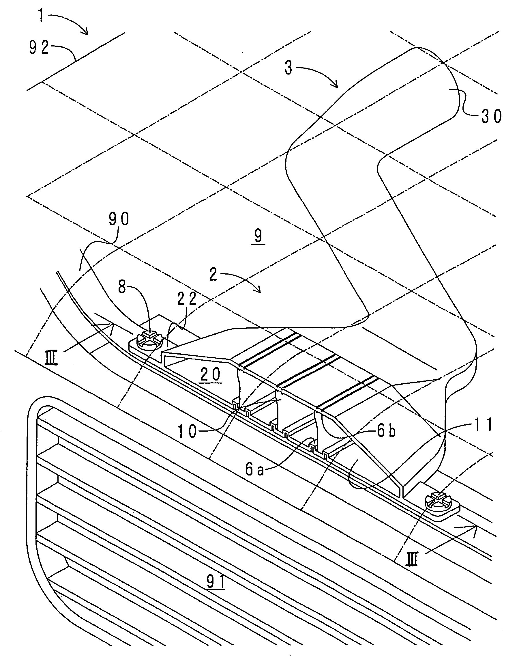
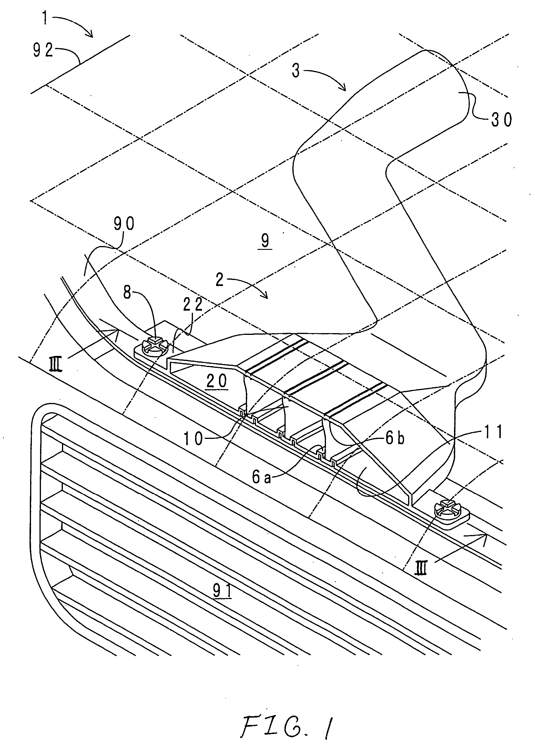
[0033] First, a description will be given of the construction of an air intake duct in accordance with a first embodiment of the invention. FIG. 1 shows a perspective view of the air intake duct of this embodiment. It should be noted that a hood panel is shown by a wire frame (shown by chain lines in the drawing) due to the convenience of explanation. FIG. 2 shows an exploded perspective view of the air intake duct. FIG. 3A shows a cross-sectional view taken along line III-III in FIG. 1. As shown in these drawings, an air intake duct 1 is comprised of an inlet port section 2, an air passage section 3, a rib member 10, and stopper members 6a and 6b. It should be noted that a wall section of the invention is made up of the inlet port section 2 and the air passage section 3. Air passages 11 are formed in the interiors of the inlet port section 2 and the air passage section 3.

[0034] The inlet port section 2 is formed by injection molding polypropylene (PP). The inlet port section 2 has...

second embodiment

[0045] First, a description will be given of the construction of the air intake duct in accordance with a second embodiment of the invention. FIG. 4 shows a perspective view of the air intake duct of this embodiment. It should be noted that portions corresponding to those of FIG. 1 are denoted by the same reference numerals. FIG. 5 shows an exploded perspective view of the air intake duct. It should be noted that portions corresponding to those of FIG. 2 are denoted by the same reference numerals. FIG. 6 shows a cross-sectional view taken along line VI-VI in FIG. 4. It should be noted that portions corresponding to those of FIGS. 3A to 3C are denoted by the same reference numerals.

[0046] As shown in these drawings, the stopper member 6a is formed in the shape of an annular rib. A circumferentially continuous engaging pawl 62 is formed on an upper end of the stopper member 6a. The stopper member 6a is provided in such a manner as to project from the lower wall of the inlet port sect...

third embodiment

[0048] The air intake duct in accordance with a third embodiment of the invention differs from the second embodiment in that a spring member is disposed instead of the rubber member. Further, the shapes of the stopper members also differ. Furthermore, a cover member is disposed on an outer peripheral side of the spring member. Accordingly, a description will be given only of the differences.

[0049]FIG. 7 shows a cross-sectional view in a short-axis direction of the air intake duct in accordance with this embodiment. It should be noted that portions corresponding to those of FIG. 6 are denoted by the same reference numerals. FIG. 8 shows a perspective view of the stopper member of the air intake duct. It should be noted that portions corresponding to those of FIG. 5 are denoted by the same reference numerals. A spring member 4 is made of steel and has the shape of a hollow truncated cone whose diameter decreases gradually from the lower side toward the upper side, as shown in FIG. 7....


PUM


Abstract

An air intake duct is disposed in an engine compartment and has wall sections for forming an air passage for introducing air into a combustion chamber of an engine. A support member is disposed on at least a portion of the wall sections, wherein the support member is shrunk when a compressive force of a predetermined value or more is applied from the outside to the wall sections, and at least a portion of the support member is elastically restored when the compressive force decreases.

Description

[0001] This application is based on Japanese Patent Application No. 2004-059456, which is incorporated herein by reference. BACKGROUND OF THE INVENTION [0002] 1. Field of the Invention [0003] The present invention relates to an air intake duct for introducing outside air into a combustion chamber of an engine. [0004] 2. Description of the Related Art [0005] An air intake duct is disposed on a most upstream side of an induction system for allowing the outside and a combustion chamber to communicate with each other (e.g., refer to JP2003-314393 Å). The air intake duct has a wall section for partitioning an air passage. An inlet port section is formed at an upstream end of the wall section. The inlet port section is open in the vicinity of a front edge of an engine compartment. The inlet port section is secured to an upper portion of a radiator upper support of a radiator. Meanwhile, a downstream end of the wall section is connected to a dirty side (an upstream side of an air element) ...

Claims


Application Information

Patent Timeline
Patent Type & Authority Applications(United States)
IPC IPC(8): B60H1/00F02M35/10B60K13/02F02M35/16
CPCB60K13/02
Inventor KINO, HITOSHI
Owner TOYODA GOSEI CO LTD
Why Eureka
Try Eureka