Metal snow guard

a technology of metal snow guards and snow traps, applied in snow traps, building repairs, soldering equipment, etc., can solve the problems of oxidizing or crystallizing, interfering with the attachment of the guard, etc., and achieve the effect of fast and efficient application of solder pas

Inactive Publication Date: 2005-10-06
SNO GEM
View PDF8 Cites 3 Cited by
  • Summary
  • Abstract
  • Description
  • Claims
  • Application Information

AI Technical Summary

Benefits of technology

[0011] In accordance with a important aspect, the amount of solder on the underside of the snow guard is controlled so that there is no excess solder running down from the snow guard and ruining the appearance of the expensive metal roof. Preferably, the layer of solder is enough to solder the snow guard without running of the solder from the snow guard down along the metal roof below the snow guard.
[0012] In one embodiment, the layer of soldering material is in the form of spaced projections on the underside of the base. When heated the soldering materials flows to cover uneven, that is non-flat surfaces on the underside of the base and / or roof surface to improve the soldering area between the snow guard and the roof. The person doing the soldering will feel that the snow guard shifts or moves relative to the roof as the projections melt and spread the soldering material from the melting projections into the spaces between projections. Usually, this person will sense a sinking downwardly of the snow guard as the projections melt.
[0015] The amount of solder and amount of flux layered on the underside of the snow guard is such that it will not run or wick down the roof. The amount of heat applied is such that the solder merely forms a meniscus at the edge of the snow guard. Also, viewing holes or openings may be provided in the snow guard base so that when applying heat to do the liquidification of the soldering material, the installer may view the formation of the liquid solder to prevent overheating or underheating of the solder, roof material and snow guard material. In one embodiment of the invention, the solder material will be seen to be bubbling in a small viewing hole or holes to allow the installer to ascertain the state of the soldering operation occurring beneath the base of the snow guard.
[0017] In accordance with another aspect of the disclosure, the upper viewing hole may be sized smaller in the upper layer of a panel of the base than the larger hole in the lower panel of the base containing the solder paste. The smaller viewing hole may be sized to receive a fastener if it is desired to use a fastener to secure the snow guard to the roof. Of course, if fasteners are used, the snow guard could be made without any solder material in the holes in the lower base. On the other hand, the fasteners can be driven through solder paste and driven into the roof. The preferred solder past may be screen printed onto the underside of the base for a fast and efficient way of applying the solder paste to the base. If desired, to avoid contamination and to seal the solder against oxidizing, a cover sheet may be releasably attached to cover the flux and / or flux solder layer on the snow guard.

Problems solved by technology

Often, the snow guards are not used for several months after there manufacture and the uncovered or unsealed solder may oxidize or crystallize and interfere with the attachment of the guard to the roof.

Method used


Image

  • Metal snow guard
  • Metal snow guard
  • Metal snow guard

Examples


Embodiment Construction

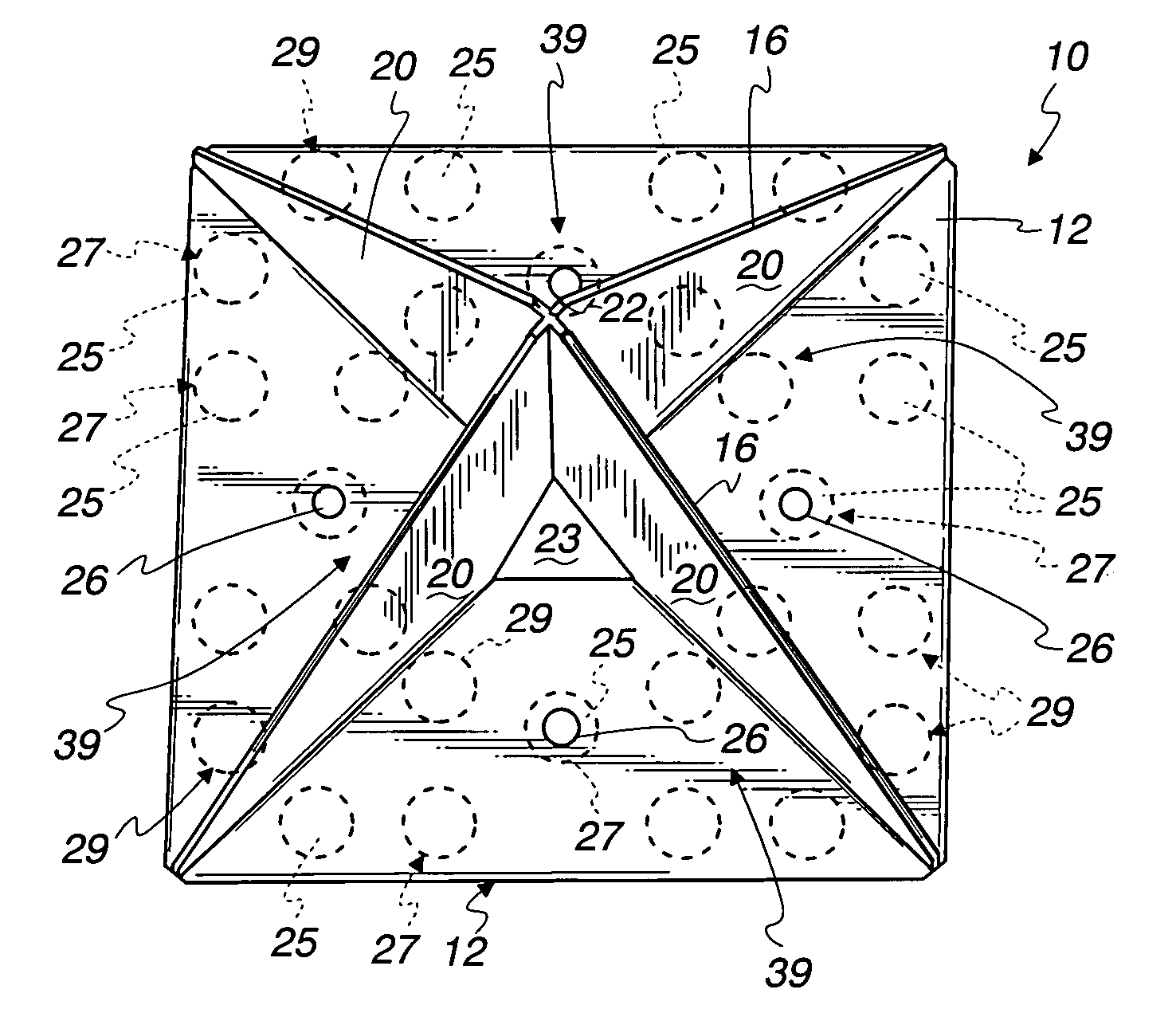
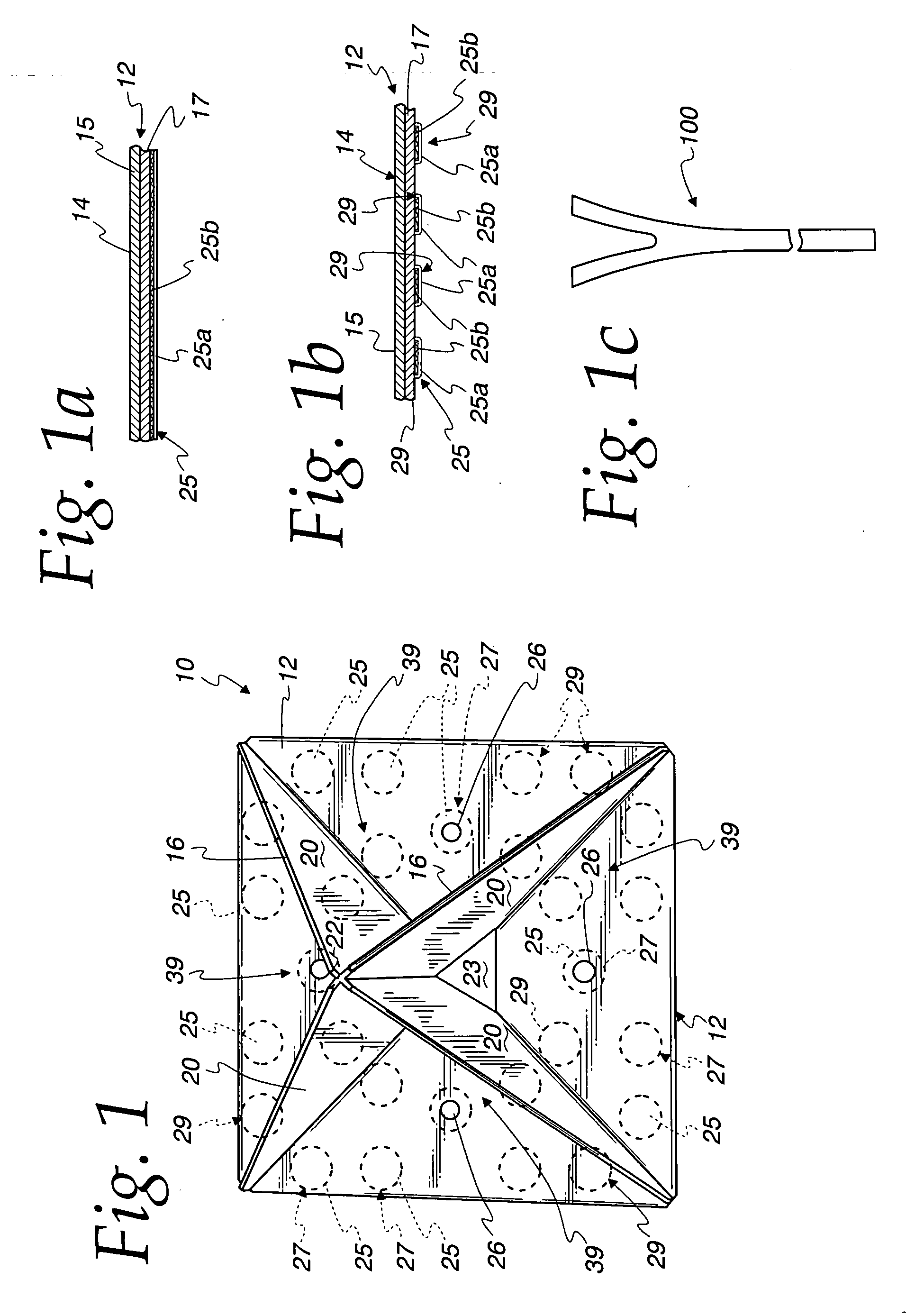
[0046] As shown in the drawings for purposes of illustration, the invention is embodied in a snow guard 10 which is fastened to a downwardly inclined roof or a downwardly inclined portion of building facia, or the like to restrain ice and / or snow from sliding downwardly onto people, automobiles, or the like. For the sake of convenience, the term “roof” shall be used generally to mean not only a roof but also an inclined surface of a facia, covered walkway structure, or whatever the snow guard is fastened to. The snow guard has a base 12 that is fastened to the inclined roof and includes upstanding members 20 projecting upwardly from the base and for engaging the ice or snow accumulated on the roof. The roof may be made of various materials and shapes. Typically, the metal roof formed of a series of adjacent metal sections or panels that have upwardly projecting side edges flanges that are overlapped to form a seam between adjacent panels. In this type of roof, the metal sections hav...


PUM

PropertyMeasurementUnit
temperatureaaaaaaaaaa
widthaaaaaaaaaa

Abstract

A method of making a metal snow guard is disclosed. The snow guard has a solid layer of soldering material on its base to be heated and melted with application of heat to the upper side of the snow guard to solder the base to an underlying metal roof. The soldering material may be applied as spaced spots or projections providing a rough surface on the underside of the snow guard. The amount of solder and / or flux in the solid layer is limited so that the solder and / or flux does not flow outwardly from the snow guard and run down the metal roof thereby damaging or marring the metal roof surface. The snow guards may be formed of a few pieces of sheet metal. The projections of soldering material may be formed by forcing a paste of solder and flux through spaced holes in a plate or screen onto the base.

Description

CROSS-REFERENCE TO RELATED APPLICATION [0001] This application claims the benefit of U.S. Provisional Application Ser. No. 60 / 356,049, filed Feb. 11, 2002, which is incorporated by reference in its entirety herein.FIELD OF THE INVENTION [0002] This invention relates to snow guards for restraining ice and snow from sliding down inclined surfaces of buildings, particularly inclined roofs. BACKGROUND OF THE INVENTION [0003] One particularly successful snow guard having a gem-like appearance and made of plastic and usually of colored plastic is disclosed in U.S. Pat. Nos. 5,901,507 and 5,471,700 to Smeja, et al. The present invention is not limited to this particular shape or kind of snow guard but is applicable to various other shapes and kinds of snow guards. The particular shapes and kinds of snow guards illustrated and described herein are the preferred embodiments of the invention and are merely exemplary. [0004] The snow guards shown in the aforesaid patents have been very success...

Claims


Application Information

Patent Timeline
Patent Type & Authority Applications(United States)
IPC IPC(8): E04D13/10
CPCE04D13/10
Inventor SMEJA, GEORGESMEJA, MICHAEL V.LIVINGSTON, TROY
Owner SNO GEM
Why Eureka
Try Eureka