Pivot pin structure

a technology of pivot pins and pins, which is applied in the field of enclosure-type pivot pin structures, can solve the problems of increasing the difficulty of processing operations, complicated assembling process of pivot pins, and complex structure of pivot pins as a whole, and achieve the effect of improving the structure of pivot pins

Inactive Publication Date: 2012-10-11
FIRST DOME
View PDF13 Cites 8 Cited by
  • Summary
  • Abstract
  • Description
  • Claims
  • Application Information

AI Technical Summary

Benefits of technology

[0014]It is therefore a primary object of the present invention to provide an improved pivot pin structure including an assembling section formed on a surface of the pivot pin for assembling with at least one bridge member. The bridge member has a pivot section, which rotatably encloses the assembling section of the pivot pin. On the assembling section are disposed multiple ridge sections (or raised sections) and valley sections (or recessed sections) non-parallel to the axis of the pivot pin. The ridge sections and valley sections are formed in a cross-sectional direction of the pivot pin normal to or approximately normal to the axis of the pivot pin and continuously arranged on the surface thereof. By means of the ridge sections and valley sections of the assembling section, the pivot pin can be assembled with the bridge member in an interference-fit manner to naturally provide a guide and restriction effect and lubricant-reserving effect. Therefore, the bridge member is restricted to only rotate around the pivot pin without axially displacing.
[0017]It is still a further object of the present invention to provide the above pivot pin structure, which has an embossed section and a depression positioned near the embossed section. When pressing the bridge member onto the embossed section of the pivot pin in an interference-fit manner, the metal chips produced under the thrust force between the bridge member and the embossed section are pushed into the depression. The metal chips are received in the depression so that it is unnecessary to further clean up the metal chips as in the prior art. Moreover, the depression also provides an area for a tool to clamp in torque test for assembly of the pivot pin and the bridge member. Therefore, after the embossed section of the pivot pin is assembled with the bridge member affixed to the case of the electronic device, the depression and the clamp marks formed on the depression are all concealed by the bridge member. This solves the problem of ruin of the appearance of the pivot pin due to the tool marks.

Problems solved by technology

This complicates the assembling process of the pivot pin 10 and the bridge member 20.
Also, the structure of the pivot pin as a whole becomes more complicated.
This increases difficulty in the processing operation.

Method used


Image

  • Pivot pin structure
  • Pivot pin structure
  • Pivot pin structure

Examples


Embodiment Construction

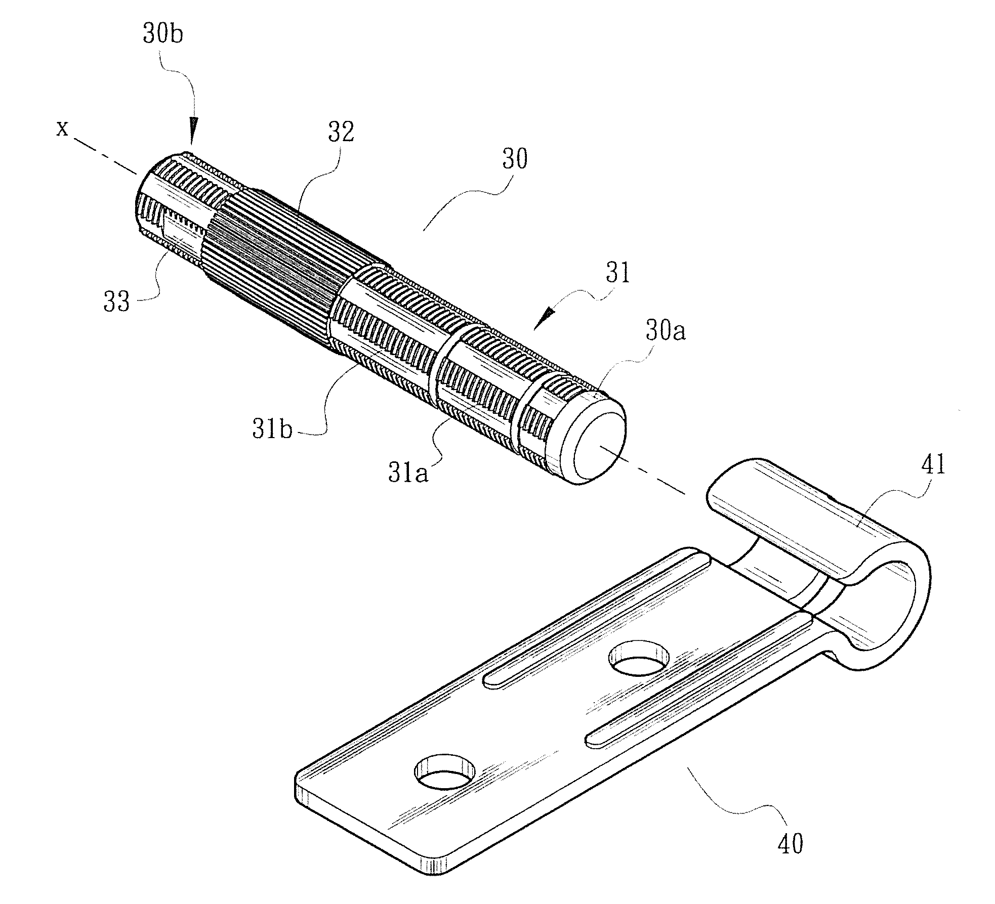
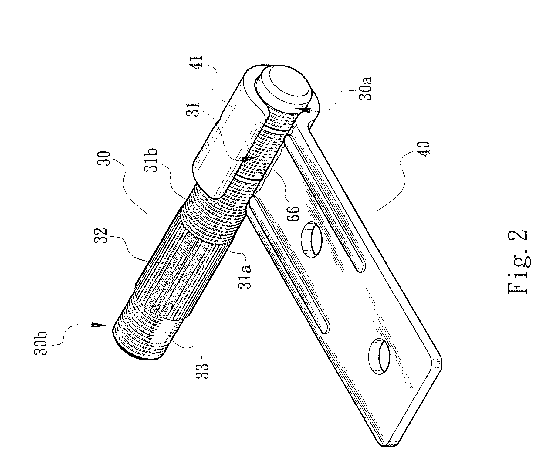
[0025]Please refer to FIGS. 2 and 3. The pivot pin structure of the present invention includes a pivot pin 30 and a bridge member 40 assembled with the pivot pin 30. The pivot pin 30 has the form of a pole body. The pivot pin 30 has an axis χ and an assembling section 31 for assembling with the bridge member 40. The pivot pin 30 further has an embossed section 32 adjacent to the assembling section 31.

[0026]In a preferred embodiment, the bridge member 40 is fixedly mounted on a cover or display screen 61 of an electronic device 60 (as shown in FIG. 5). The bridge member 40 has the form of a board body, having a pivot section (or bight section) 41 in which the assembling section 31 of the pivot pin 30 is enclosed.

[0027]In the preferred embodiment of the present invention, the assembling section 31 is formed with multiple ridge sections (or raised sections) 31a and valley sections (or recessed sections) 31b non-parallel to the axis χ. Preferably, the ridge sections 31a and valley secti...


PUM


Abstract

A pivot pin structure includes an assembling section formed on a surface of the pivot pin for assembling with at least one bridge member. The bridge member has a pivot section, which rotatably encloses the assembling section of the pivot pin. On the assembling section are disposed multiple ridge sections and valley sections non-parallel to the axis of the pivot pin. The ridge sections and valley sections are formed in a cross-sectional direction of the pivot pin normal to or approximately normal to the axis of the pivot pin and continuously arranged on the surface thereof. By means of the ridge sections and valley sections of the assembling section, the pivot pin can be assembled with the bridge member in an interference-fit manner to naturally provide a guide and restriction effect and lubricant-reserving effect. Therefore, the bridge member is restricted to only rotate around the pivot pin without axially displacing.

Description

BACKGROUND OF THE INVENTION[0001]1. Field of the Invention[0002]The present invention relates generally to an enclosure-type pivot pin structure applied to a display screen of an electronic device, and more particularly to a pivot pin with simplified structure. The pivot pin can be easily assembled with a bridge member in an interference-fit manner to naturally provide a guide and restriction effect and lubricant-reserving effect. Therefore, the bridge member is restricted to only rotate around the pivot pin without axially displacing.[0003]2. Description of the Related Art[0004]Various conventional pivot pin structures have been developed and applied to rotatable covers or display screens of electronic devices such as cellular phones, laptop computers and digital cameras. For example, FIG. 1 shows an assembly of a conventional pivot pin 10 and bridge member 20.[0005]As shown in FIG. 1, the pivot pin 10 has the form of a pole body, including a pivot section 11 with a polished surfac...

Claims


Application Information

Patent Timeline
Patent Type & Authority Applications(United States)
IPC IPC(8): F16C11/04
CPCE05Y2900/606E05D3/02E05D5/04Y10T403/32951G06F1/1681E05D2005/102E05D5/10
Inventor LIN, CHANG YUMAI, CHIEN CHENG
Owner FIRST DOME
Why Eureka
Try Eureka