
System and method for measurements of depth and velocity of instrumentation within a wellbore

a technology of depth and velocity measurement and wellbore, which is applied in the direction of instruments, borehole/well accessories, surveys, etc., can solve the problems of different velocity of survey tools within the wellbore from the measured velocity of wires or cables, and errors in the determination of absolute depth

Active Publication Date: 2005-10-06
GYRODATA
View PDF24 Cites 11 Cited by
  • Summary
  • Abstract
  • Description
  • Claims
  • Application Information

AI Technical Summary

Benefits of technology

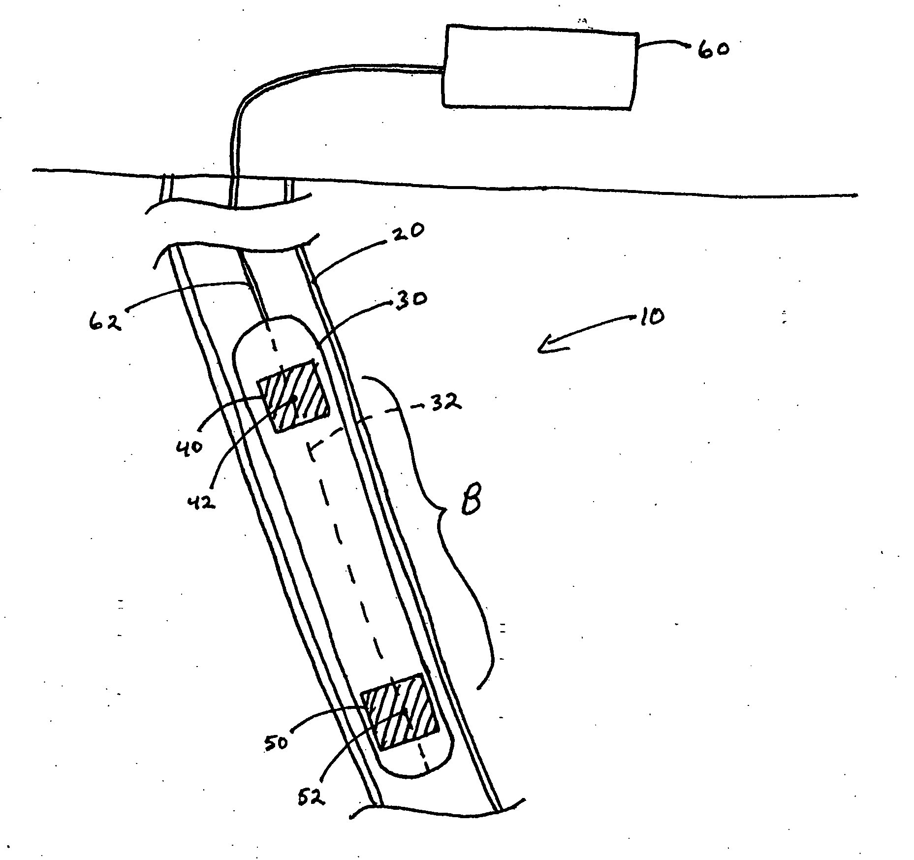
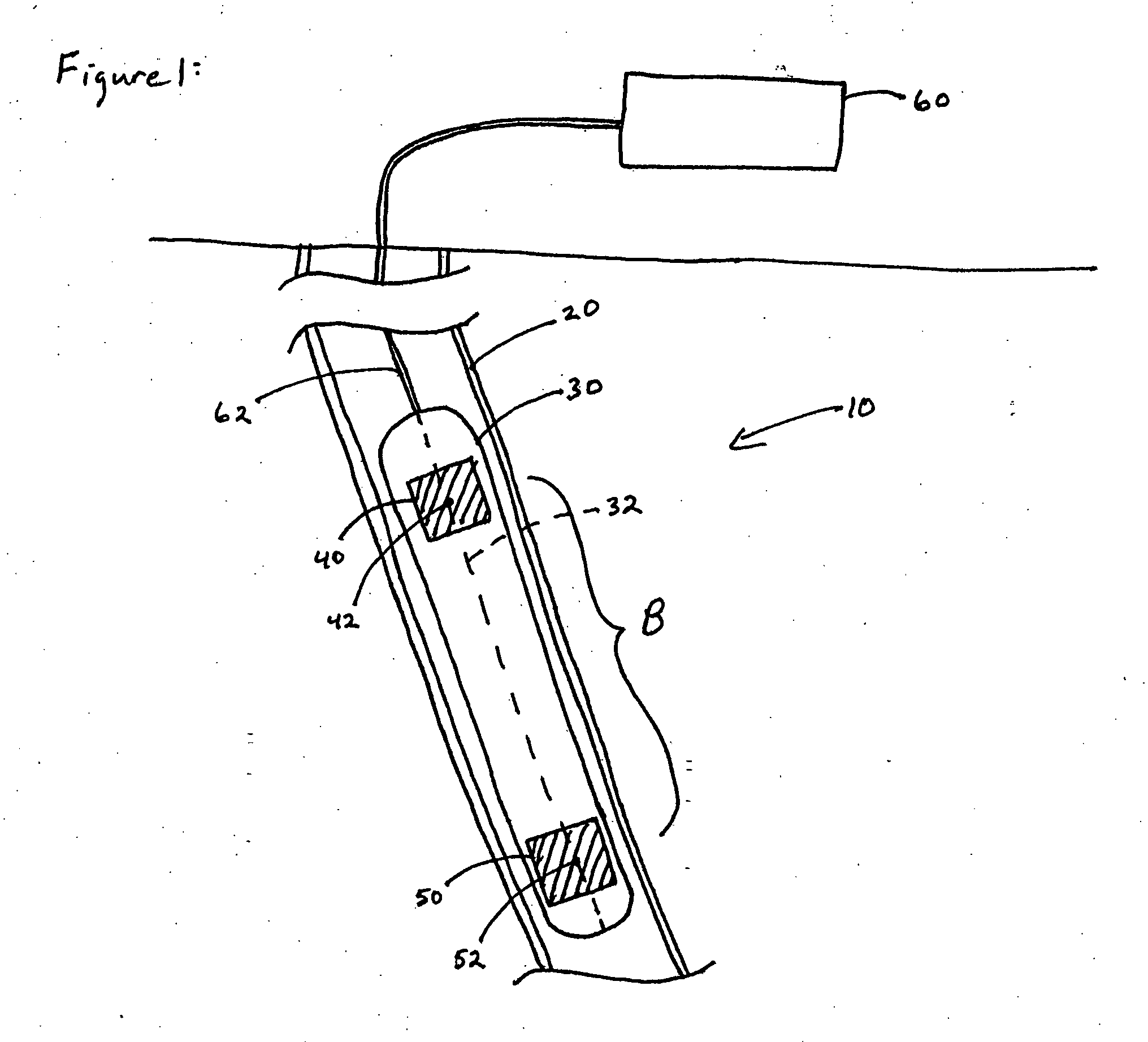
"The patent describes a survey tool that can be used in a wellbore to measure depth and velocity. The tool has two acceleration sensors that generate signals that indicate acceleration along the wellbore axis. By calculating the difference between these signals, the tool can determine the depth and velocity of the downhole portion of the wellbore. The technical effect of this invention is to provide a more accurate and efficient means for surveying wellbores."

Problems solved by technology

However, due to various distortions, the cumulative length of the pipe sections or of the wire while within the wellbore can differ from the cumulative length measured at the surface, resulting in errors in the determination of the absolute depth.
However, as with the surface-based depth measurements described above, surface-based velocity measurements do not provide a sufficient accuracy (e.g., within only a few centimeters) to tell when two geophysical sensors with significant along-hole separation pass the same geological formation within only a few centimeters of accuracy.
In addition, these effects can result in the velocity of the survey tool within the wellbore differing from the measured velocity of the wire or cable at the surface.
However, such procedures are vulnerable to noise in the detected acceleration, which results in a drift of the depth measurement from the true depth of the survey tool.
It has been difficult, and will likely continue to be difficult, to get such inertial navigation systems to work without providing aiding data such as surface-based depth measurements or updates of the depth obtained while the survey tool is stationary (i.e., zero-velocity updates) to remove this drift.

Method used


Image

  • System and method for measurements of depth and velocity of instrumentation within a wellbore
  • System and method for measurements of depth and velocity of instrumentation within a wellbore
  • System and method for measurements of depth and velocity of instrumentation within a wellbore

Examples


Embodiment Construction

[0021] Certain embodiments described herein provide a true downhole-based system for measuring a depth, a velocity, or both a depth and a velocity of a downhole portion with sufficient accuracy for logging and drilling applications.

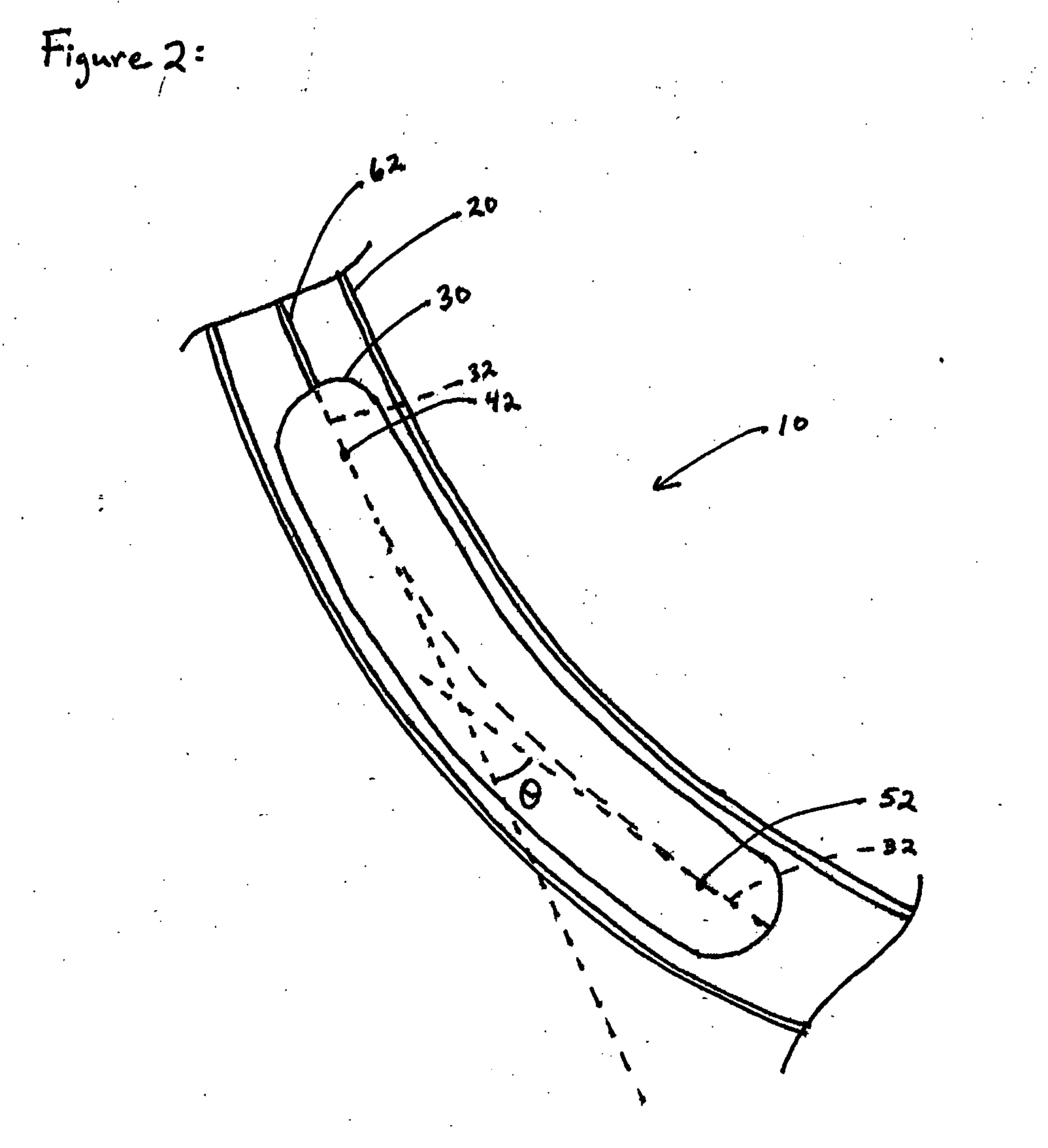
[0022]FIG. 1 schematically illustrates a survey tool 10 compatible with embodiments described herein for use in a wellbore 20. The survey tool 10 comprises a downhole portion 30 having an axis 32. The downhole portion 30 is adapted to move within the wellbore 20 with the axis 32 generally parallel to the wellbore 20. The survey tool 10 further comprises a first acceleration sensor 40 mounted at a first position 42 within the downhole portion 30. The first acceleration sensor 40 is adapted to generate a first signal indicative of an acceleration of the first acceleration sensor 40 along the axis 32. The survey tool 10 further comprises a second acceleration sensor 50 mounted at a second position 52 within the downhole portion 30. The second position 52 is...


PUM


Abstract

A survey tool for use in a wellbore includes a downhole portion having an axis. The downhole portion is adapted to move within the wellbore with the axis generally parallel to the wellbore. The survey tool further includes a first acceleration sensor mounted at a first position within the downhole portion. The first acceleration sensor is adapted to generate a first signal indicative of an acceleration of the first acceleration sensor along the axis. The survey tool further includes a second acceleration sensor mounted at a second position within the downhole portion. The second position is spaced from the first position by a non-zero distance along the axis. The second acceleration sensor is adapted to generate a second signal indicative of an acceleration of the second acceleration sensor along the axis. The survey tool further includes a controller adapted to receive the first signal and the second signal and to calculate a depth, a velocity, or both a depth and a velocity of the downhole portion in response to the first signal and the second signal.

Description

CLAIM OF PRIORITY [0001] This application is a continuation of U.S. patent application Ser. No. 10 / 811,317, filed Mar. 26, 2004, which claims the benefit of U.S. Provisional Application No. 60 / 539,234, filed Jan. 26, 2004, both of which are incorporated in their entirety by reference herein.BACKGROUND OF THE INVENTION [0002] 1. Field of the Invention [0003] The present application relates generally to systems and method for determining the depth, the velocity, or both the depth and the velocity of an instrumentation package within a wellbore. [0004] 2. Description of the Related Art [0005] Surface-based wellbore depth measurements are typically made periodically during wellbore drilling for the exploration of oil and gas deposits to determine the absolute depth of the drilling tool within the wellbore. In such measurements, the depth of the drilling tool is typically determined by surface measurements of the lengths of the pipe sections inserted into the wellbore between the drillin...

Claims


Application Information

Patent Timeline
Patent Type & Authority Applications(United States)
IPC IPC(8): E21B47/022E21B47/04G01P3/42G01P7/00
CPCE21B47/022G01P7/00E21B47/04
Inventor EKSETH, ROGERGREENSMITH, MARTYRN IAN
Owner GYRODATA
Learn More