

Unit-type heat exchanger
a heat exchanger and unit-type technology, applied in indirect heat exchangers, lighting and heating apparatus, stationary conduit assemblies, etc., can solve the problems of preventing the impairment of the performance of the heat exchange cycle, and achieve the effect of increasing the contact area, effective heat exchange, and increasing the for
- Summary
- Abstract
- Description
- Claims
- Application Information
AI Technical Summary
Benefits of technology
Problems solved by technology
Method used
Image

Examples
Embodiment Construction
[0030] Embodiments of the present invention will be described below with reference to the drawings. Throughout the drawings, like parts are designated by like reference numerals and will not be described repeatedly.
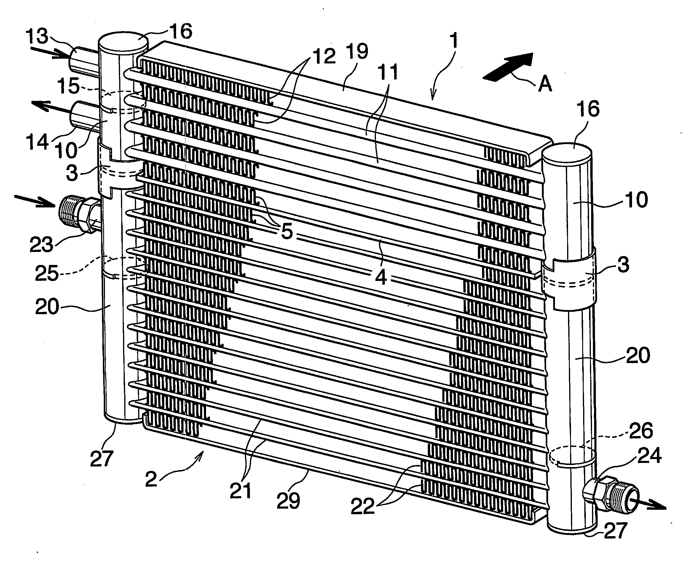
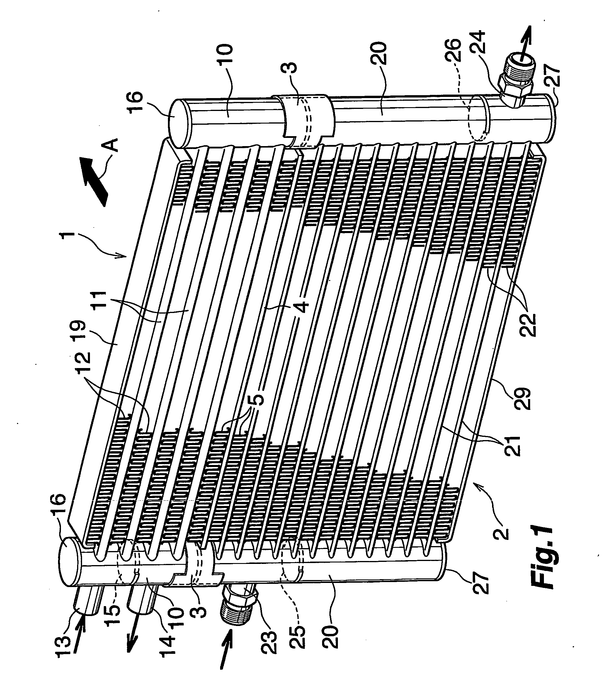
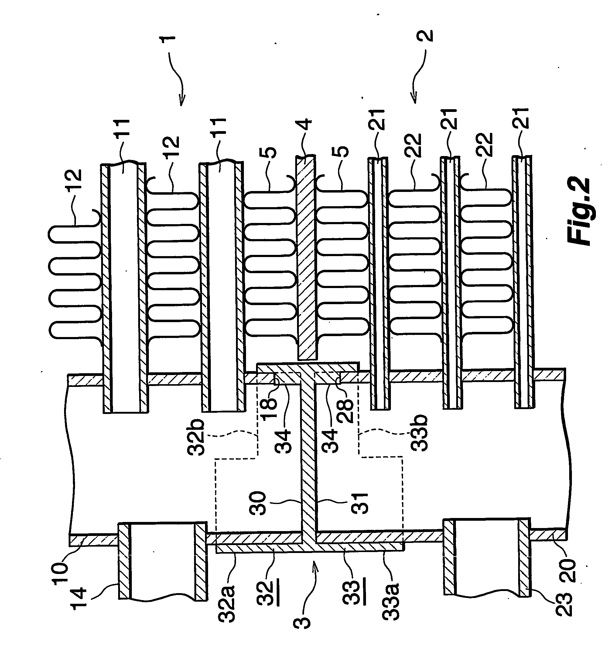
[0031]FIG. 1 shows the overall construction of an embodiment of unit-type heat exchanger according to the invention, and FIGS. 2 and 3 are fragmentary views of the heat exchanger. In the following description, the upper and lower sides, and left- and right-hand sides of FIG. 1 will be referred to respectively as “upper,”“lower,”“left” and “right.”
[0032] With reference to FIG. 1, the unit-type heat exchanger is adapted for use in motor vehicles, and comprises an oil cooler 1 and a condenser 2 for motor vehicle air conditioners which are provided in a vertical plane, with the former positioned above the latter.
[0033] The oil cooler 1 comprises two aluminum vertical headers 10 arranged in parallel as laterally spaced apart from each other, parallel aluminum flat heat excha...
PUM
 Abstract
Description
Claims
Application Information