
Spindle and spool for welding gun

a welding gun and spindle technology, applied in the field of spindle and spindle for welding guns, can solve the problems of insufficient efforts to develop a lighter, lighter welding gun for emergency, hobby, home and/or recreational use, and the typical weight of welding guns. achieve the effect of quick disconn

Active Publication Date: 2005-10-06
M K PRODS
View PDF17 Cites 23 Cited by
  • Summary
  • Abstract
  • Description
  • Claims
  • Application Information

AI Technical Summary

Benefits of technology

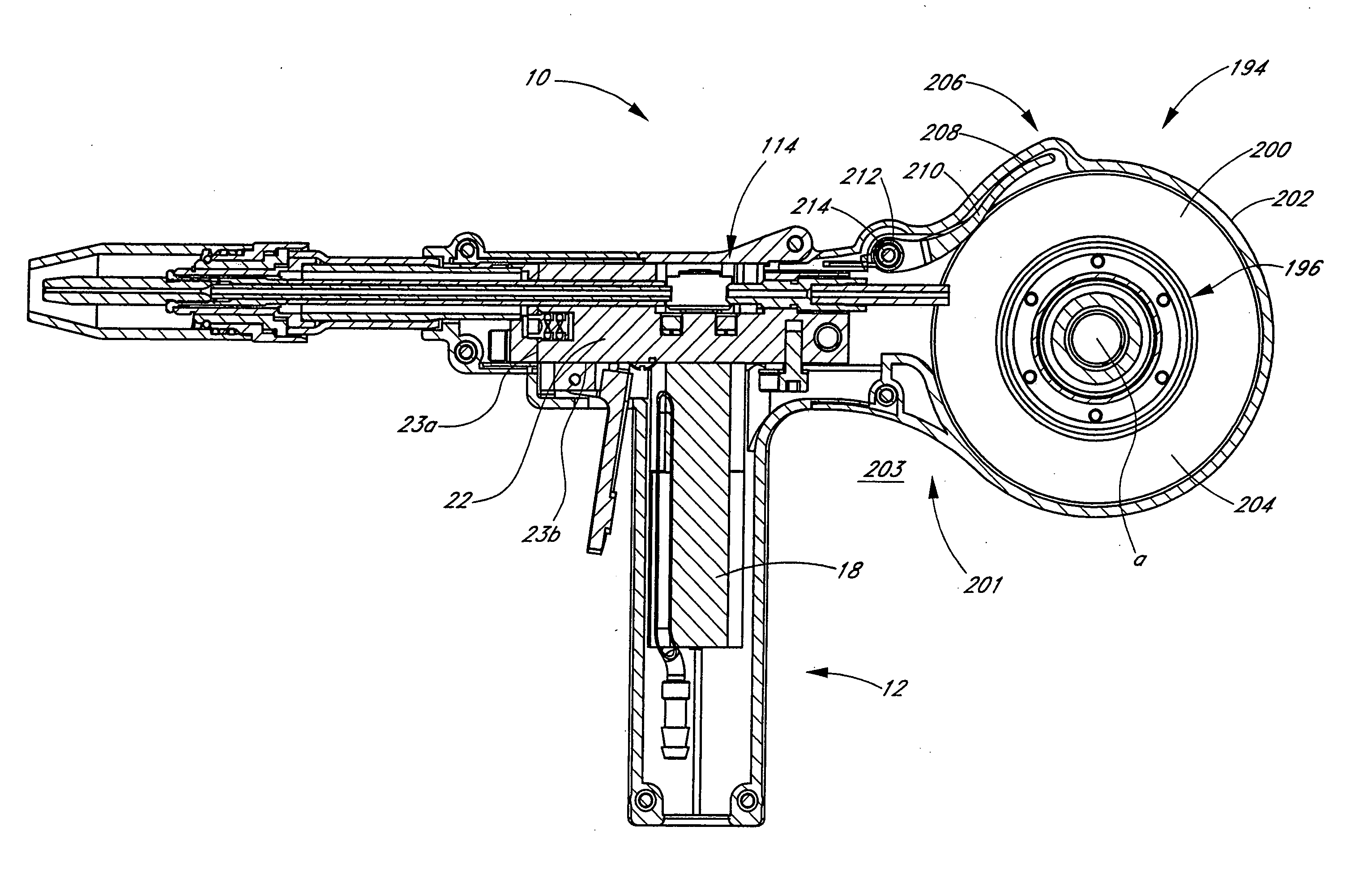
[0009] Accordingly, one embodiment of the present invention comprises a welding gun including a wire spool comprising a body that forms an outer surface for supporting the welding wire and an inner surface. The inner surface has an outer edge, an inner edge and a first portion extending from the inner edge, a second portion extending from the outer edge and a support portion positioned between the first and second portions. The support portion has an inner diameter that is smaller or equal to the inner diameter of the first and second portions. The first portion forms at least one retaining surface. The at least one retaining surface has a portion defining an inner diameter that is larger than the inner diameter of the support surface and smaller than the remaining portions of the first portion. The at least one retaining surface being positioned away from the inner edge. The gun also includes a spindle having an outer surface for supporting the wire spool and quick disconnect assembly. The assembly is configured for releasably coupling the wire spool to the spindle. The quick disconnect assembly comprises a locking element moveable between a first position configured in which the locking element engages the at least one retaining surface and a second position in which the locking element disengages the at least one retaining surface.
[0010] Accordingly, one embodiment of the present invention is a wire spool comprising a body that forms an outer surface for supporting the welding wire and an inner surface. The inner surface has an outer edge, an inner edge and a first portion extending from the inner edge, a second portion extending from the outer edge and a support portion positioned between the first and second portions. The support portion has an inner diameter that is smaller or equal to the inner diameter of the first and second portions. The first portion forms at least one retaining surface. The at least one retaining surface has a portion defining an inner diameter that is larger than the inner diameter of the support surface and smaller than the remaining portions of the first portion. The at least one retaining surface being positioned away from the inner edge.
[0011] Other some embodiments the spool has a fully loaded weight of less than or equal to about 0.5 pounds.

Problems solved by technology

To meet the demands of these industrial applications, welding guns are typically relatively heavy and bulky instruments.
Despite this need, efforts to date to develop a smaller, lighter welding gun for emergency, hobby, home and / or recreational uses have not been satisfactory.

Method used


Image

  • Spindle and spool for welding gun
  • Spindle and spool for welding gun
  • Spindle and spool for welding gun

Examples


Embodiment Construction

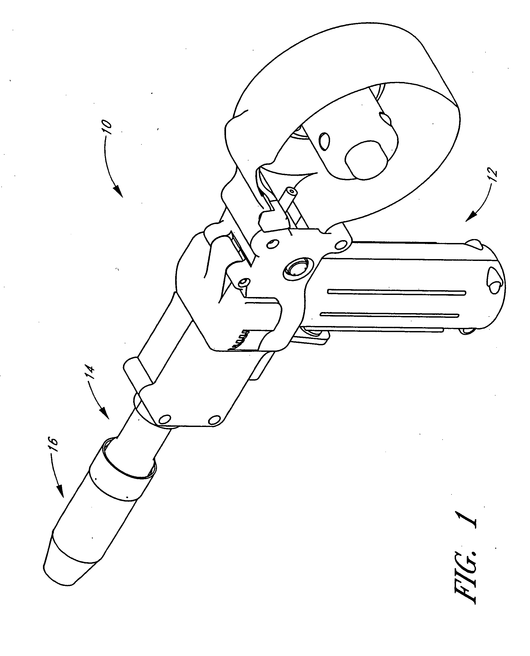
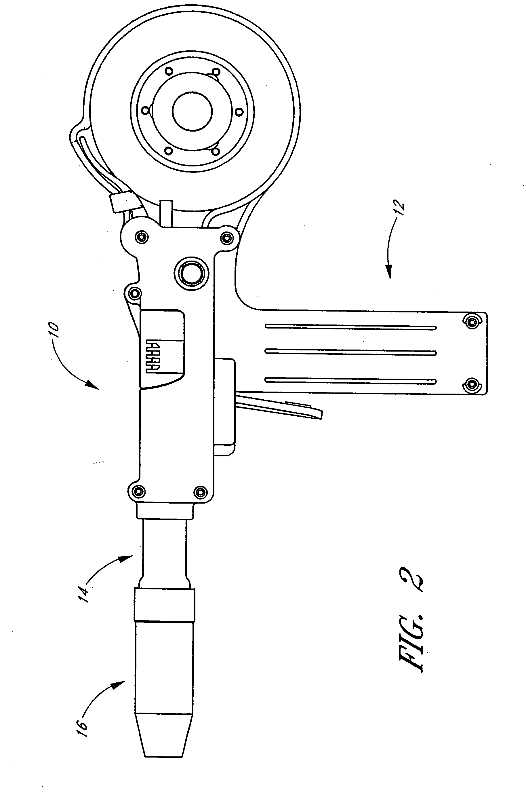
[0031]FIGS. 1 and 2 are a perspective and side views of an exemplary embodiment of a welding gun 10. In the illustrated embodiment, the gun 10 includes a handle 12, a torch barrel section 14 and a welding tip 16. FIG. 3 is a cross-sectional view of the gun 10 that illustrates a motor 18, which is positioned inside the handle 12. The longitudinal axis l1 of the handle 12 and the motor 18 preferably lie transverse to the longitudinal axis l2 of the gun 10 and, more preferably, substantially perpendicular to the axis l2 of the gun 10. The illustrated gun 10, therefore, is a “pistol grip” welding gun. The motor 18 and other portions of the gun are preferably covered by a substantially rigid, two-piece molded plastic casing 20a, 20b, which is best seen in FIG. 4 and will be described in more detail below.

[0032] With particular reference to FIGS. 3 and 4, the gun 10 includes a power block 22, which is preferably made of aluminum. In the illustrated embodiment, the power block is generall...


PUM

PropertyMeasurementUnit
weightaaaaaaaaaa
diameteraaaaaaaaaa
inner diameteraaaaaaaaaa

Abstract

A welding gun includes a motor, a wire feed mechanism, a power block, a welding tip, a and a cup. A substantially rigid shell surrounds the motor to form a handle. The gun includes a spindle, a spool and a quick disconnect mechanism for coupling the spool to the spindle.

Description

PRIORITY INFORMATION [0001] This application claims the priority benefit under 35 U.S.C. § 119(e) of Provisional Application ______, filed Apr. 5, 2004 under attorney docket no. MKPROD.062PR.BACKGROUND OF THE INVENTION [0002] 1. Field of the Invention [0003] This invention relates to welding guns and, in particular, to a spool and a spindle for a welding gun. [0004] 2. Description of the Related Art [0005] A goose neck metal inert gas (MIG) welding gun generally comprises a handle, a wire feed mechanism, and a torch gun or barrel. The welding gun typically also includes a gas tube for supplying inert gas to the end of the torch barrel. Some welding guns also include a water tube for supplying cooling water to the end of the torch gun or barrel. “Push-pull” MIG welding guns typically also include motor for driving the wire feed mechanism. [0006] There are three general types of welding guns: pistol grip, goose neck and in-line welding guns. In a pistol grip gun, the motor is located ...

Claims


Application Information

Patent Timeline
Patent Type & Authority Applications(United States)
IPC IPC(8): B23K9/12B23K9/133B23K9/173
CPCB23K9/173B23K9/133
Inventor KENSRUE, MILO M.NGUYEN, TRUNG DINH
Owner M K PRODS
Learn More