Switchable assembly bearing with hydraulic damping

Inactive Publication Date: 2005-10-06
VIBRACOUSTIC
View PDF5 Cites 4 Cited by
  • Summary
  • Abstract
  • Description
  • Claims
  • Application Information

AI Technical Summary

Benefits of technology

[0008] An object of the present invention is to further develop an assembly bearing in a manner such that it will

Problems solved by technology

A drawback of the known assembly bearing, however, is that the central aperture strongly reduces the surface area available for the membrane.
This has a deleterious effect o

Method used


Image

  • Switchable assembly bearing with hydraulic damping
  • Switchable assembly bearing with hydraulic damping
  • Switchable assembly bearing with hydraulic damping

Examples


Embodiment Construction

[0024] The following description of the preferred embodiment(s) is merely exemplary in nature and is in no way intended to limit the invention, its application, or uses.

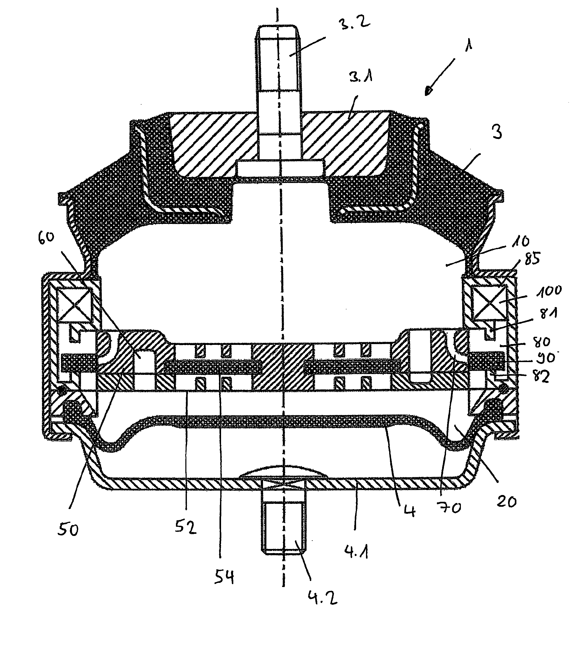
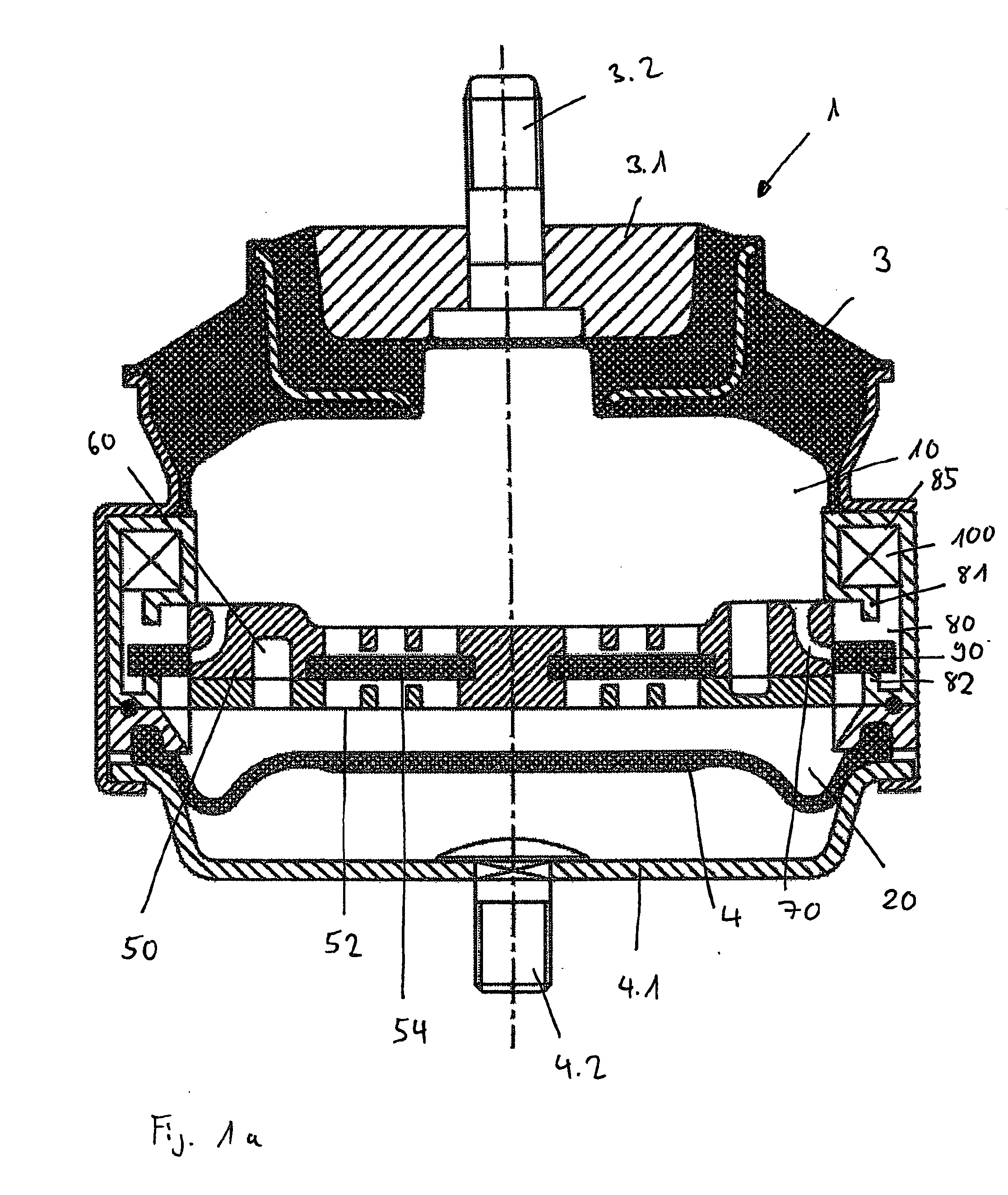
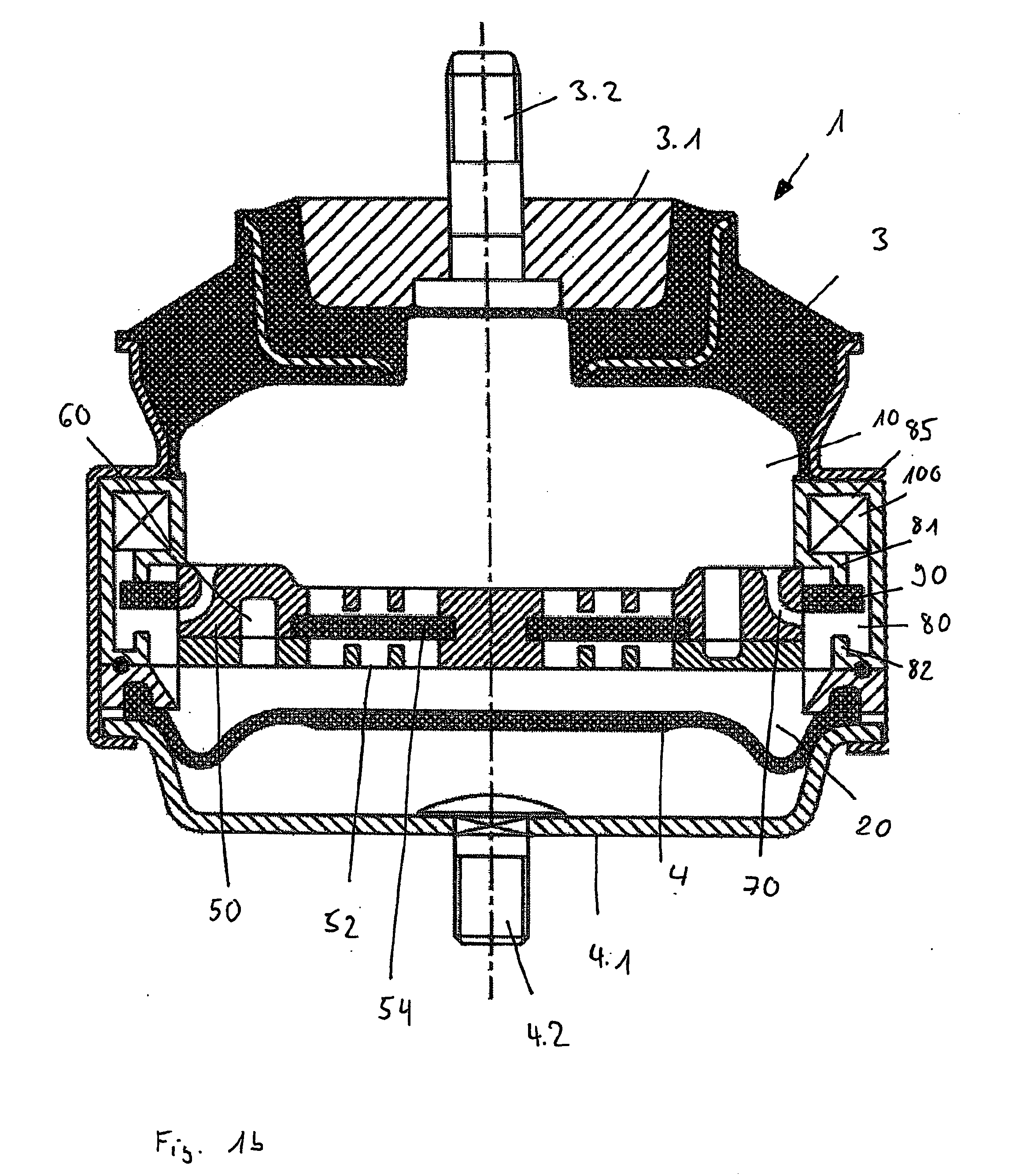
[0025]FIGS. 1a and 1b show a hydraulically damped assembly bearing 1 provided with a working chamber 10 and a compensation chamber 20 which are filled with a common hydraulic fluid. Working chamber 10 is limited by a wall 3 having a truncated conical shape and made of an elastic material, known as the bearing spring. Compensation chamber 20 is limited at the bottom by a cup-shaped wall 4, also made of an elastic material, for example by an air bellows capable of absorbing volume without creating pressure. On the side of the engine, a peripheral wall 3 receives a bearing plate 3.1. The plate is provided with a protruding screw bolt 3.2 for fastening to the engine. Between working chamber 10 and compensation chamber 20 is located a dividing wall 50 in which is disposed a membrane cage 52 for receiving a membrane 54. I...


PUM


Abstract

The invention relates to a switchable assembly bearing that comprises at least one working chamber and one compensation chamber which are separated by a dividing wall. The working chamber and compensation chamber are hydraulically interconnected by means of a damping channel, in addition to at least one other damping channel which can be closed by means of the sealed arrangement of a shut-off body which can be displaced along a displacement path. The other damping channel is formed and arranged in relation to the axis of symmetry of the bearing in such a way that the forces acting on the shut-off body by means of the hydraulic fluid counterbalance each other.

Description

CROSS-REFERENCE TO RELATED APPLICATIONS [0001] This application is a National Stage of International Application No. PCT / EP03 / 03124, filed Mar. 26, 2003. This application claims the benefit of German Patent Application 102 13 996.2, filed Mar. 27, 2002. The disclosures of the above applications are incorporated herein by reference.FIELD OF THE INVENTION [0002] The invention relates to a switchable assembly bearing with hydraulic damping, particularly for supporting drive assemblies and / or gearbox assemblies in motor vehicles. The bearing comprises at least one working chamber and one compensation chamber that are separated from one another by a dividing wall. The working chamber and compensation chamber are interconnected hydraulically by means of a damping channel, and at least one additional damping channel that can be closed by means of a shut-off body displaceable along a displacement path. The shut-off body is capable of providing a seal in cooperation with an associated seat. ...

Claims


Application Information

Patent Timeline
IPC IPC(8): F16F13/26
CPCF16F13/26
Inventor FREUDENBERG, TILLMANMOOG, ERHARD
Owner VIBRACOUSTIC
Why Eureka
Try Eureka