Plasma display panel and manufacture method thereof
- Summary
- Abstract
- Description
- Claims
- Application Information
AI Technical Summary
Benefits of technology
Problems solved by technology
Method used
Image

Examples
first embodiment
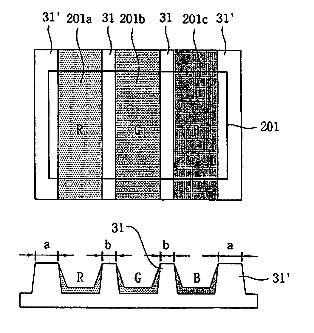
[0040]FIGS. 5A and 5B are views illustrating barrier rib structures of discharge cell structures in a plasma display panel according to a first embodiment of the present invention. In other words, FIG. 5A illustrates the barrier rib structure in a stripe-type discharge cell structure according to the present invention, and FIG. 5B illustrates the barrier rib structure in a well-type discharge cell structure according to the present invention.
[0041] As shown in FIGS. 5A and 5B, the inventive plasma display panel includes a first barrier rib 31 and a second barrier rib 31′ each disposed at a rear substrate. The first barrier rib 31 partitions red (R), green (G) and blue (B) sub-pixels 201a, 201b and 201c. The second barrier rib 31′ partitions a unit pixel 201, which is constituted of the R, G, B sub-pixels 201a, 201b and 201c, and an adjacent unit pixel. On the assumption that the first barrier rib 31 partitioning the R, G, B sub-pixels 201a, 201b and 201c has a width of “b” and the ...
second embodiment
[0044]FIGS. 6A and 6B are views illustrating barrier rib structures and black matrix structures of discharge cell structures in a plasma display panel according to a second embodiment of the present invention. In other words, FIG. 6A illustrates the barrier rib structure and the black matrix structure in a stripe-type discharge cell structure, and FIG. 6B illustrates the barrier rib structure and the black matrix structure in a well-type discharge cell structure.
[0045] In FIGS. 6A and 6B, the inventive barrier rib structures are the same as those of the first embodiment and therefore, their descriptions are omitted. However, in the inventive plasma display panel, a black matrix having a predetermined pattern is formed at a front substrate. It is desirable that a barrier rib has a white-color material to compensate for luminance reduction caused by the black matrix of the front substrate in the PDP.
[0046] Like a conventional art, in the inventive plasma display panel having the str...
third embodiment
[0051]FIGS. 8A and 8B are views illustrating barrier rib structures of discharge cell structures in a plasma display panel according to a third embodiment of the present invention. In other words, FIG. 8A illustrates the barrier rib structure of a stripe-type discharge cell structure, and FIG. 8B illustrates the barrier rib structure of a well-type discharge cell structure.
[0052] In FIGS. 8A and 8B, the barrier rib structures are the same as those of the first embodiment of the present invention and therefore, their descriptions are omitted. However, the barrier rib structures are all formed of black-color material.
[0053] As such, in the inventive PDP having the barrier rib structure, color mixture caused by light emission of each unit pixel can be improved, and the barrier rib can be formed of black-color material, thereby decreasing reflectance against external light and improving a contrast characteristic.
[0054]FIGS. 9A through 9D are views sequentially illustrating a method f...
PUM
 Abstract
Description
Claims
Application Information
 - R&D
- Intellectual Property
- Life Sciences
- Materials
- Tech Scout
- Unparalleled Data Quality
- Higher Quality Content
- 60% Fewer Hallucinations
Browse by: Latest US Patents, China's latest patents, Technical Efficacy Thesaurus, Application Domain, Technology Topic, Popular Technical Reports.
© 2025 PatSnap. All rights reserved.Legal|Privacy policy|Modern Slavery Act Transparency Statement|Sitemap|About US| Contact US: help@patsnap.com