Processor control of an audio transducer

a technology of audio transducer and processor, which is applied in the direction of audible signalling system, instruments, signalling system, etc., can solve the problems of high voltage and little flexibility

Active Publication Date: 2005-10-06
FLOYD BELL
View PDF11 Cites 35 Cited by
  • Summary
  • Abstract
  • Description
  • Claims
  • Application Information

AI Technical Summary

Benefits of technology

[0007] The invention is a circuit for generating sound in the audible frequency range and includes the conventional input voltage terminals for powering the circuit. An audio transducer is driven by a driving circuit that includes at least one energy storing inductor and one or more electronic switches adapted for energizing the energy-storing inductor and for transferring energy from the inductor to the audio transducer. A microprocessor circuit or controller generates a stream of pulses at a controlled rate and with a controlled duty cycle under program control.

Problems solved by technology

A drawback of the use of one type of piezoelectric transducer, piezoelectric benders, to generate the tones is the relatively high Q of such circuit elements, requiring a precise drive frequency for maximum output, and the high voltages needed to generate the

Method used


Image

  • Processor control of an audio transducer
  • Processor control of an audio transducer
  • Processor control of an audio transducer

Examples


Embodiment Construction

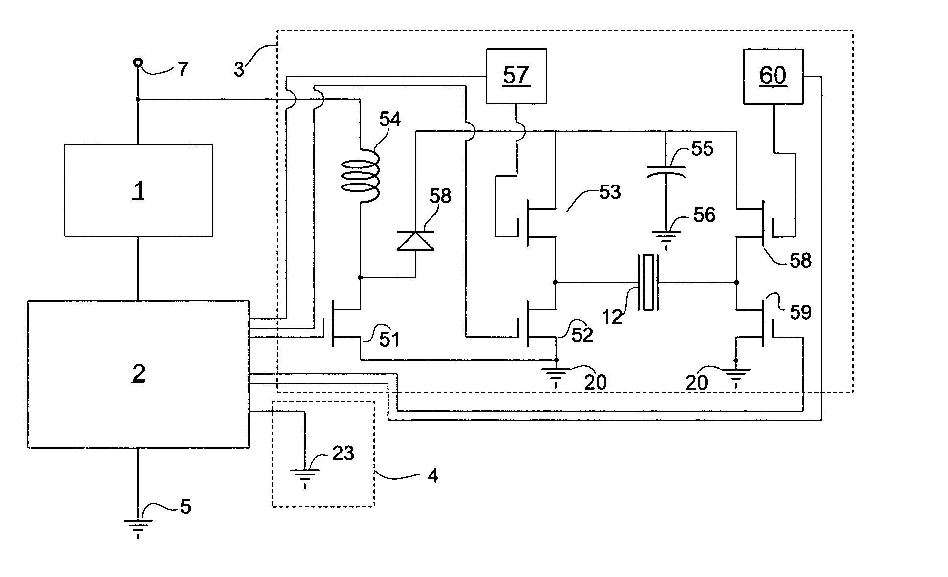
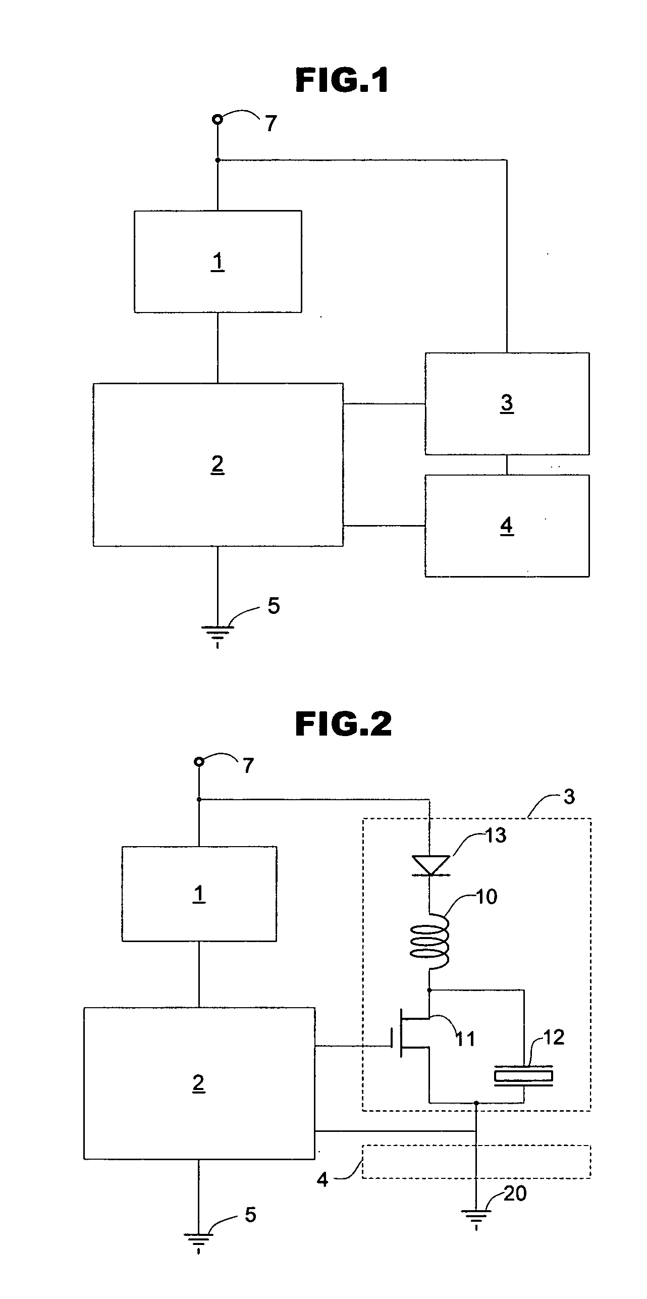
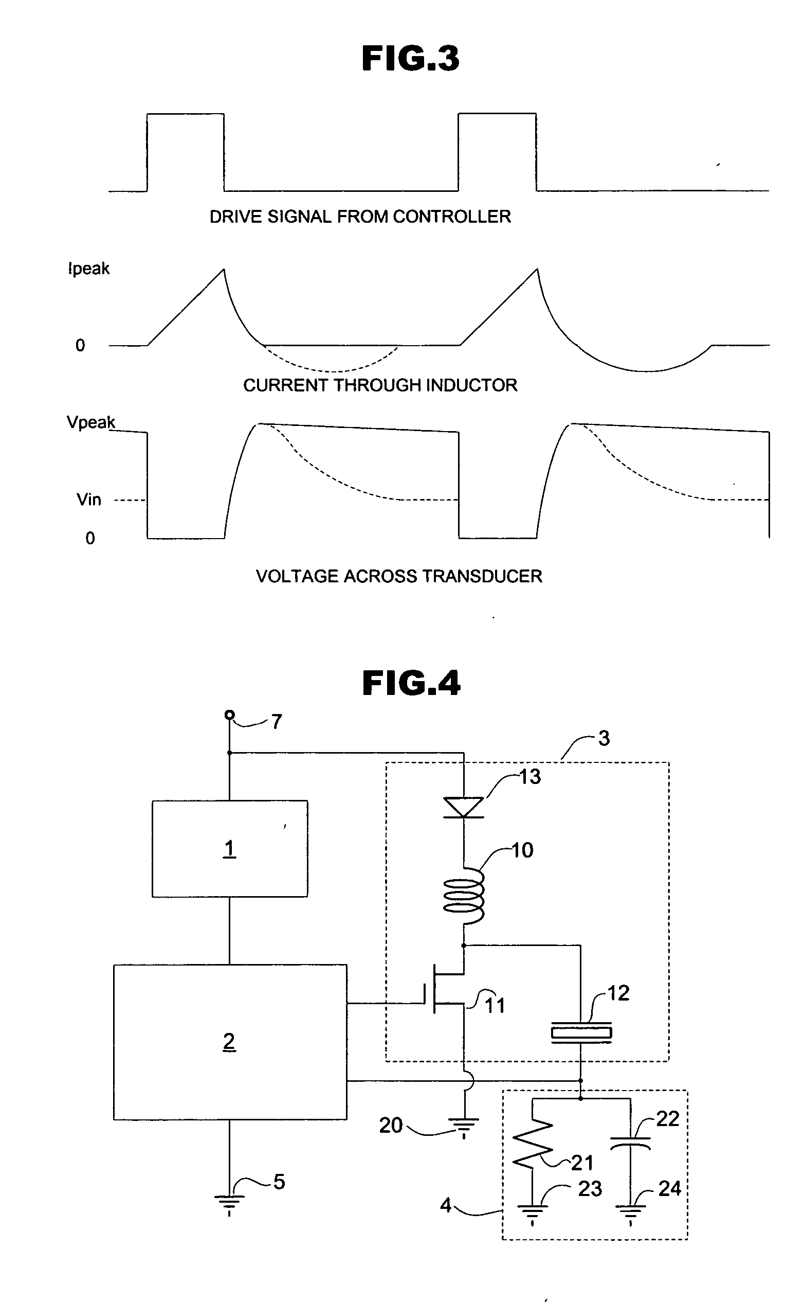
[0020] The following discusses a controller function. It is meant that a controller is any device for performing the functions of a finite state machine, defined as a model of computation consisting of a set of states, a start state, an input alphabet, and a transition function that maps input symbols and current states to a next state. Computation begins in the start state with an input string. It changes to new states depending on the transition function. Examples of a finite state machine are microprocessors, microcontrollers, PLAs, PALs, and memories combined with sequential clocking.

[0021] Directing attention to FIG. 2, a detailed electric circuit diagram of a preferred embodiment is shown. An input voltage is applied between a positive terminal 7 and ground 5. This input voltage is regulated by the voltage regulator 1 and applied to controller 2 in a method well known to the practice, as, for example, by a 78L05 voltage regulator. Controller 2 is a programmed controller such ...


PUM


Abstract

A controller, either a microprocessor or finite state machine, is used to generate a pulse train whose frequency and duty cycle can be varied to alter the frequency and amplitude of the output of a driven audio transducer. The ability to control both frequency and amplitude allows programmatic synthesis of many audio effects such as steady tones, warbles, beeps, sirens and chimes with no hardware or circuit changes. The transducer can be a piezoelectric bender or a speaker. The output of the controller controls a switch that builds current in an inductor when the switch is on. When the switch is turned off, the energy stored in the inductor is dumped into the audio transducer, either directly or through intermediate capacitor storage. This allows the generation of voltages across the transducer many times the supply voltage. By the use of two outputs from the controller the drive circuit can be duplicated with the duplicate driving the other terminal of the audio transducer with a signal out of phase from the original signal, the resulting push-pull drive can quadruple the output power. The ability to programmatically modify the frequency and amplitude within the controller allows the use of a feedback input to an internal voltage discrimination circuit to modify the audio signal in response to a variety of inputs. The audio transducer drive frequency can be adjusted to maximize a feedback signal related to the drive power. This allows adaptive maximization of the output for resonant transducers such as piezoelectric benders. The control signal can be the ambient noise so the output amplitude is louder with high ambient noise and at a less annoying level when there is no background noise.

Description

BACKGROUND OF THE INVENTION [0001] 1. Field of the Invention [0002] This invention generally relates to electronic sound generating devices. More particularly the invention relates to circuits for controlling and driving such devices and allowing the generation of a variety of sounds from such sound generating devices. [0003] 2. Description of the Related Art [0004] Piezoelectric transducers have been commonly used for the generation of audio tones in a number of applications. They are characterized by low cost, reliability and high audio output. A drawback of the use of one type of piezoelectric transducer, piezoelectric benders, to generate the tones is the relatively high Q of such circuit elements, requiring a precise drive frequency for maximum output, and the high voltages needed to generate the high output sound levels. [0005] Traditionally piezoelectric audible alarms have been driven by square wave drives from oscillator circuits. The high voltages desirable across the driv...

Claims


Application Information

Patent Timeline
IPC IPC(8): G08B3/10
CPCG08B3/10
Inventor DRYER, JOSEPH E.
Owner FLOYD BELL
Why Eureka
Try Eureka