MMW electronically scanned antenna

an electronically scanned, antenna technology, applied in the direction of antennas, linear waveguide fed arrays, slot antennas, etc., can solve the problems of lossy feed networks, inability to fully populated discrete arrays, and high building costs of applications

Active Publication Date: 2005-10-06
RAYTHEON CO +1
View PDF8 Cites 227 Cited by
  • Summary
  • Abstract
  • Description
  • Claims
  • Application Information

AI Technical Summary

Problems solved by technology

Electronically scanned antennas for micro-millimeter-wave (MMW), or W-band, typically above 35 Ghz, applications are traditionally expensive to build and very few have been developed.
The packaging constraints and the costs associated with the electronics of these conventional approaches make a fully populated discrete array impractical.
Additionally, these designs require many levels of lossy feed networks, and the tolerance is so tight that the production cost can be relatively high.
Aperture efficiency is always an issue at W-band.

Method used


Image

  • MMW electronically scanned antenna
  • MMW electronically scanned antenna
  • MMW electronically scanned antenna

Examples


Embodiment Construction

[0014] In the following detailed description and in the several figures of the drawing, like elements are identified with like reference numerals.

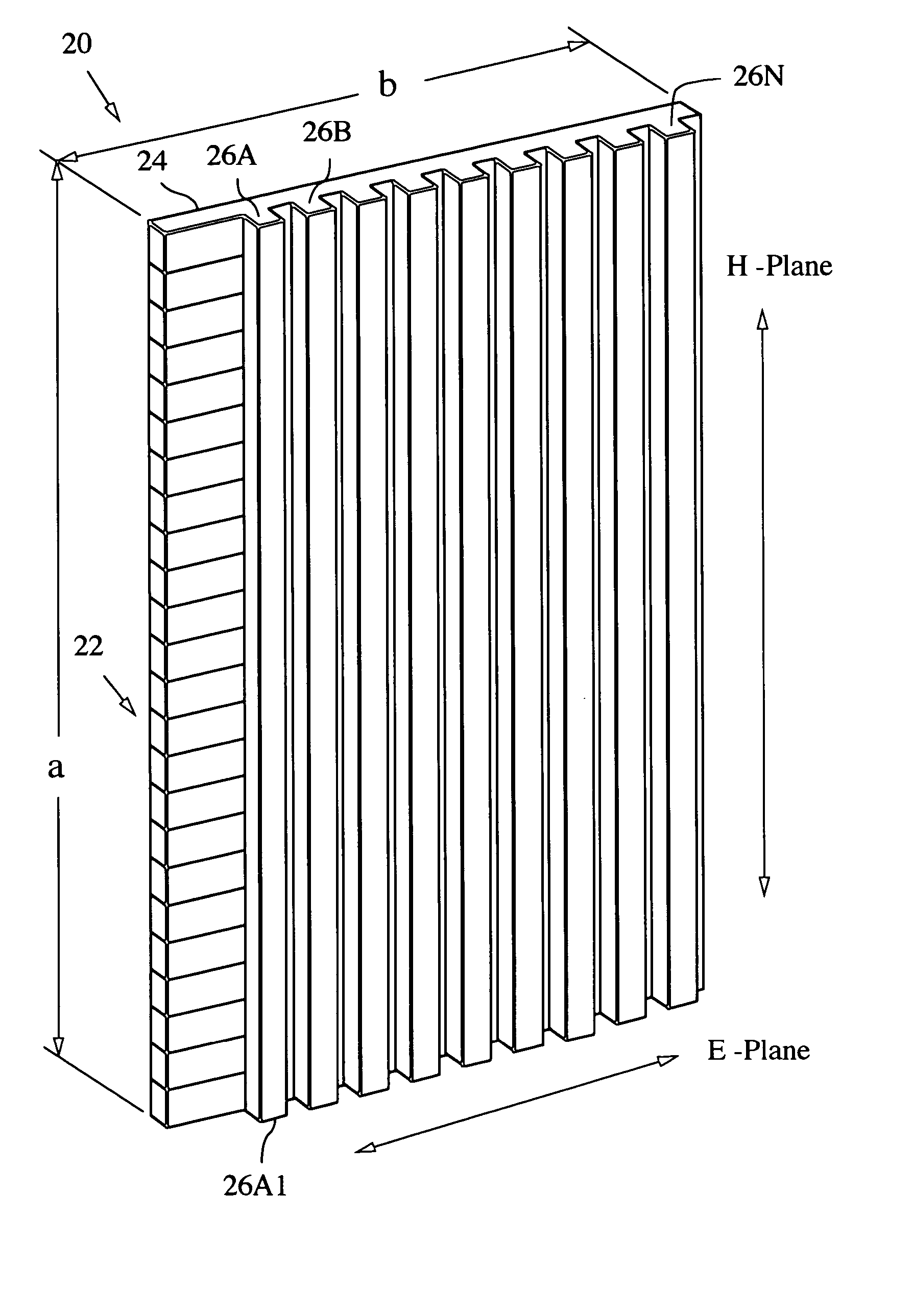
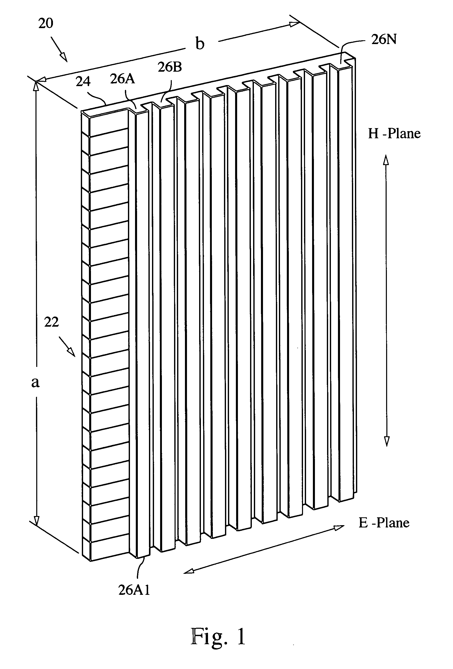
[0015] An exemplary embodiment of an electronically scanned antenna (ESA) employs CTS (continuous transverse stub) subarray panels for the aperture, which are relatively easy to build and low cost. An exemplary W-band subarray panel 20 is shown in FIG. 1; the panel can be constructed to fit within a two inch by two inch area. A CTS structure is described in U.S. Pat. No. 5,266,961, “Continuous Transverse Stub Element Devices and Methods of Making Same,” the entire contents of which are incorporated herein by reference. The array structure 20 is fabricated in this example as a metallized plastic wave guide structure, wherein a dielectric structure has metal layers plated thereon. The structure 20 includes an input edge 24, and a plurality of continuous transverse stubs 26A . . . 26N. The transverse edge surfaces of the stubs, for example, ...


PUM


Abstract

A millimeter wave (MMW) antenna array includes a continuous transverse stub (CTS) radiating aperture comprising a set of spaced continuous transverse stubs, each having a longitudinal extent. A series feed system is coupled to an excitation source for exciting the stubs with MMW electromagnetic energy having a linear phase progression along the longitudinal extent of the stubs to produce an array beam which can be scanned over a beam scan range by changing the excitation frequency.

Description

BACKGROUND [0001] Electronically scanned antennas for micro-millimeter-wave (MMW), or W-band, typically above 35 Ghz, applications are traditionally expensive to build and very few have been developed. The ones that have been demonstrated are generally implemented as a microstrip patch or slot array. The packaging constraints and the costs associated with the electronics of these conventional approaches make a fully populated discrete array impractical. Additionally, these designs require many levels of lossy feed networks, and the tolerance is so tight that the production cost can be relatively high. Aperture efficiency is always an issue at W-band. SUMMARY OF THE DISCLOSURE [0002] A millimeter wave (MMW) antenna array includes a continuous transverse stub (CTS) radiating aperture comprising a set of spaced continuous transverse stubs, each having a longitudinal extent. A feed system is coupled to an excitation source for exciting the stubs with MMW electromagnetic energy having a ...

Claims


Application Information

Patent Timeline
Patent Type & Authority Applications(United States)
IPC IPC(8): H01Q13/00H01Q21/00
CPCH01Q21/005
Inventor LEE, JAR J.WILKINSON, STEVEN R.ROSEN, ROBERT A.KRIKORIAN, KAPRIEL V.NEWBERG, IRWIN L.
Owner RAYTHEON CO
Why Eureka
Try Eureka