Immobilizer coil attachment

Active Publication Date: 2005-10-06
OMRON AUTOMOTIVE ELECTRONICS CO LTD
View PDF5 Cites 0 Cited by
  • Summary
  • Abstract
  • Description
  • Claims
  • Application Information

AI Technical Summary

Benefits of technology

[0005] The present invention is directed to providing a technique via which the manufacture of an antenna coil for device such as an immobilizer, which forms part o

Problems solved by technology

However, this process is very time consuming and the molds/apparatus which are used to make the molded body and remold it after the coil has been disposed in position, are very expensive, highly specialized pieces of equipment.
In fact, this equipment tends to be so expensive that the manufacture of such devices, at least as far as the mold

Method used


Image

  • Immobilizer coil attachment
  • Immobilizer coil attachment
  • Immobilizer coil attachment

Examples


Example

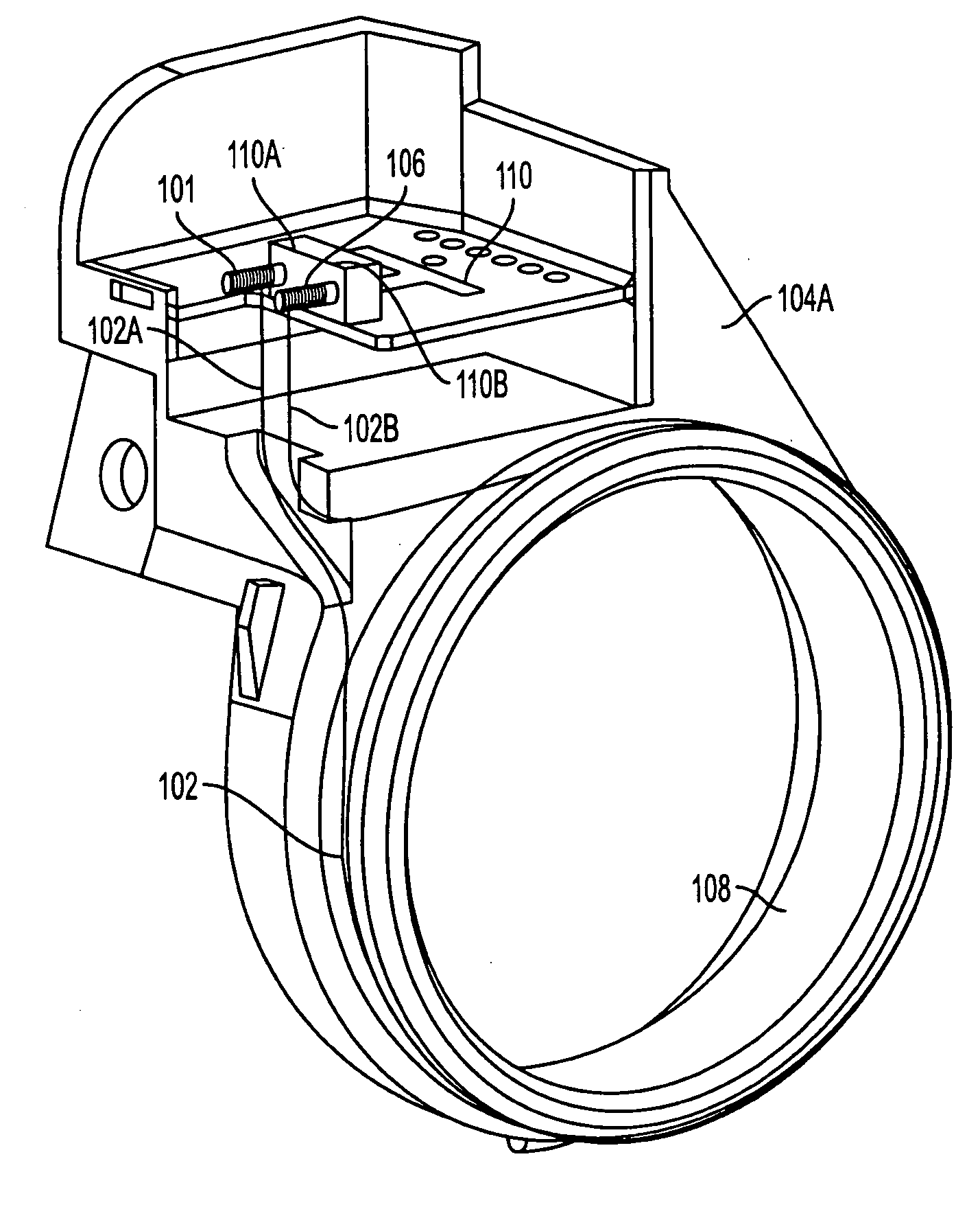
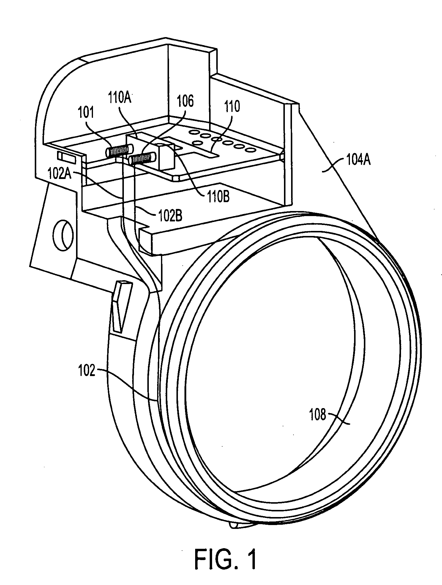
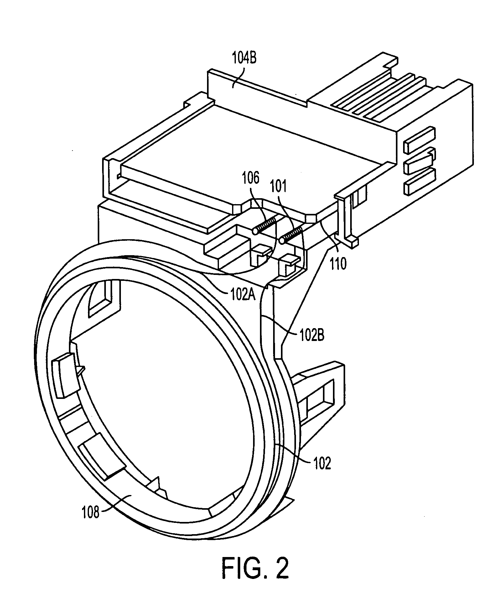
[0026] A first embodiment of the invention resides in a technique wherein one end of a length of wire has been wound onto a first connection pin 101, and then wound around a form (such as bobbin not shown) to form a coil 102 having an inner diameter which is suitable for disposition on a molded component 104 such as that illustrated any of FIGS. 1-3. The free end of the coil 102 is then wound onto a second pin 106. The coil 102 is then disposed about the circular flange 108 on the molded body. The two pins 101, 106 are then disposed in / or connection sites / structures such as 110A and 110B provided on a PCB (printed circuit board) 110 in the manner shown in any of FIGS. 1-3, for example. The pins 101, 106, coil ends 102A, 102B and connection sites / structures 110A, 110B are then interconnected by soldering.

[0027] Following this, a second molding or cover member 112 such as depicted in FIG. 4 can be disposed over the coil 102 and PCB 110 to enclose the same.

[0028] While the first embo...


PUM


Abstract

A method of making a device utilizes the step of winding a coil; disposing the coil in a predetermined position on a component which forms part of the device; connecting the ends of the coil to first and second pins by winding the ends of the coil onto the pins; and disposing the first and second pins in electrical connection with first and second connection structures formed on a PCB (printed circuit board) which is disposed in/on the component.

Description

BACKGROUND OF THE INVENTION [0001] 1. Field of the Invention [0002] The present invention relates generally to an immobilzer coil such as that used in automotive applications and more specifically to a coil immobilizer arrangement / fabrication technique that facilitates manufacture of the same. [0003] 2. Description of the Related Art [0004] In the past, coil antenna for devices such as automotive anti-theft immobilizer devices have been wound in situ on a molded body which forms part of the vehicle interior and then encased by an overmolding process. Connection pins are connected to the ends of the coil either before or after the overmolding process and are press-fitted into a plastic housing to establish an electrical connection with a PCB (printed circuit board) which is suitably arranged with the plastic housing. However, this process is very time consuming and the molds / apparatus which are used to make the molded body and remold it after the coil has been disposed in position, a...

Claims


Application Information

Patent Timeline
IPC IPC(8): B60R25/04H01Q1/32H01Q7/00
CPCB60R25/04B60R25/2063H01Q7/00H01Q1/3291B60R25/406
Inventor MELMAN, DAWN
Owner OMRON AUTOMOTIVE ELECTRONICS CO LTD
Why Eureka
Try Eureka