Zoom lens system

a zoom lens and lens body technology, applied in the field of zoom lens systems, can solve the problems of compromising compactness or high optical performance, affecting the optical performance of the lens, so as to achieve the effect of reducing manufacturing costs and simplifying the lens construction

Active Publication Date: 2005-10-06
NIKON CORP
View PDF7 Cites 58 Cited by
  • Summary
  • Abstract
  • Description
  • Claims
  • Application Information

AI Technical Summary

Benefits of technology

[0017] The present invention is made in view of the aforementioned problems and has an object to provide an internal focusing zoom lens system suitable for an auto focus SLR camera using a silver-halide film or a solid-state imaging device, carrying out focusing by moving a portion of a first lens group, having a zoom ratio of about four and an angle of view of 22° or more in the wide-angle end state, and suitable for simplifying the lens construction of the first lens group and lowering manufacturing cost without compromising compactness or high optical performance.

Problems solved by technology

However, since the moving lens group for focusing is exposed outside, when unexpected force is applied to the lens system, the focusing mechanism, in particular an auto-focusing mechanism, may be damaged.
However, it also has a problem that the moving amount for focusing largely varies in accordance with the zoom position.
However, although each example disclosed by Japanese Patent Application Laid-Open No. 6-51202 constructing the first lens group by three lens elements as a whole, two lens elements in the front lens group and one lens element in the rear lens group, is suitable for simplifying the construction and lowering the manufacturing cost, since focusing is carried out by moving only a single lens element with positive refractive power, spherical aberration, on-axis chromatic aberration and lateral chromatic aberration becomes large upon focusing a close-range object, so that it is undesirable for obtaining high optical performance.
Moreover, each example disclosed by Japanese Patent Application Laid-Open No. 2000-19398 requires five lens elements in the first lens group, three lens elements in the front lens group and two lens elements in the rear lens group, so that it is not suitable for simplifying the construction or lowering the manufacturing cost.
Furthermore, each example disclosed by Japanese Patent Application Laid-Open No. 2000-284174 requires four lens elements in the first lens group, one lens element in the front lens group and three lens elements in the rear lens group, so that it is not suitable for simplifying the construction or lowering the manufacturing cost.
However, in these disclosures, since the effective diameter of the second lens group is 25 mm or more, the vibration reduction mechanism becomes large, so that it becomes difficult to make the zoom lens system be compact.
However, in these disclosures, since the effective diameter of the vibration reduction lens group in the fourth lens group is 25 mm or more, the vibration reduction mechanism becomes large, so that it becomes difficult to make the zoom lens system be compact.

Method used


Image

  • Zoom lens system
  • Zoom lens system
  • Zoom lens system

Examples


first embodiment

[0110] The zoom lens system according to the first embodiment of the present invention is composed of, in order from an object, a first lens group having positive refractive power, a second lens group having negative refractive power, and a third lens group having positive refractive power. When a state of lens group positions varies from a wide-angle end state to a telephoto end state, a distance between the first lens group and the second lens group increases, and a distance between the second lens group and the third lens group decreases.

[0111] The first lens group is composed of, in order from the object, a 1A lens group G1A having positive refractive power and a 1B lens group G1B having positive refractive power. Focusing from infinity to a close-rang object is carried out by moving only the 1B lens group G1B to the object.

[0112] With this construction, it can be prevented to expose movable lens group for focusing, so that it is advantageous for auto focus. Moreover, by compo...

example 1

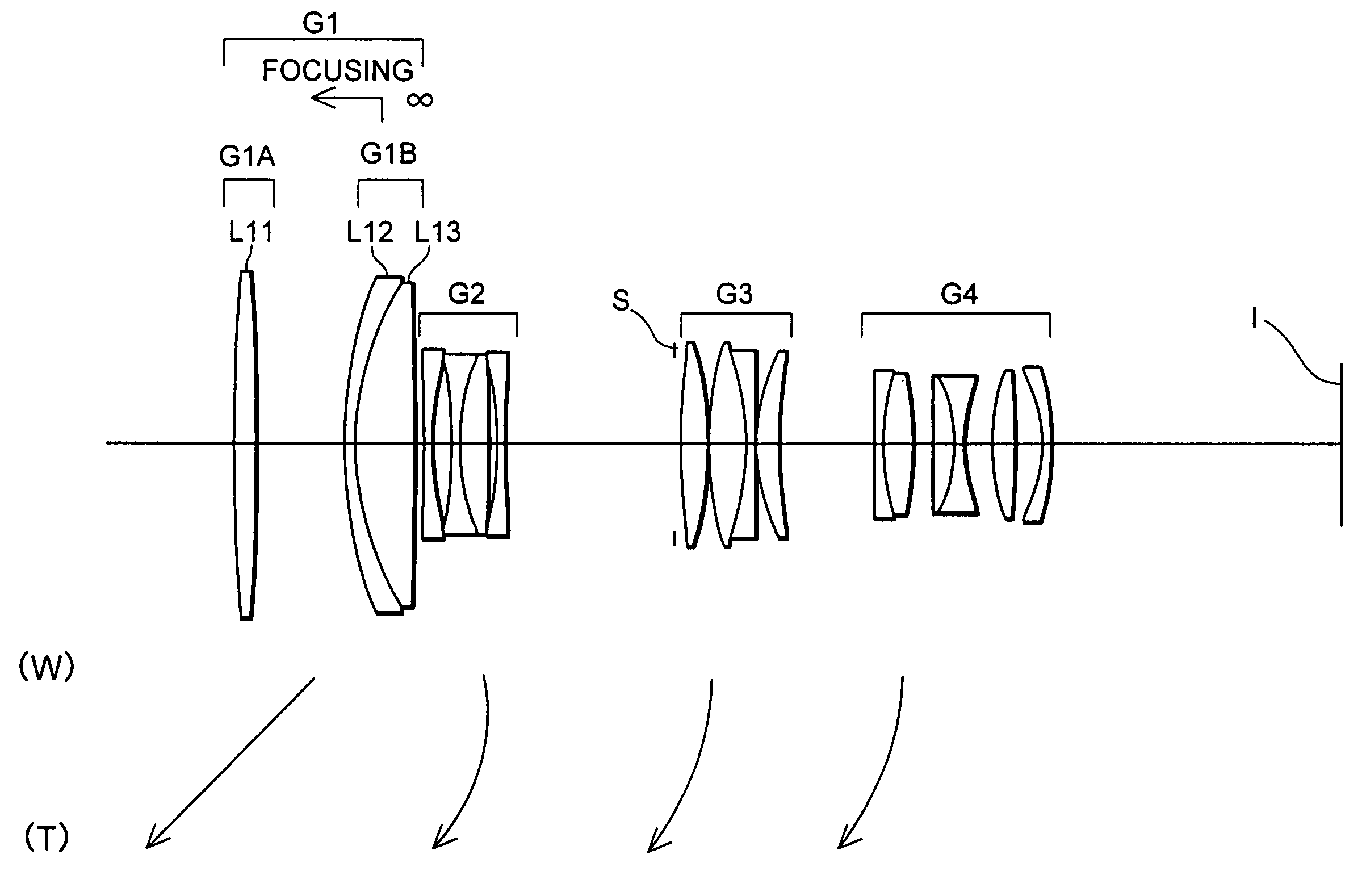
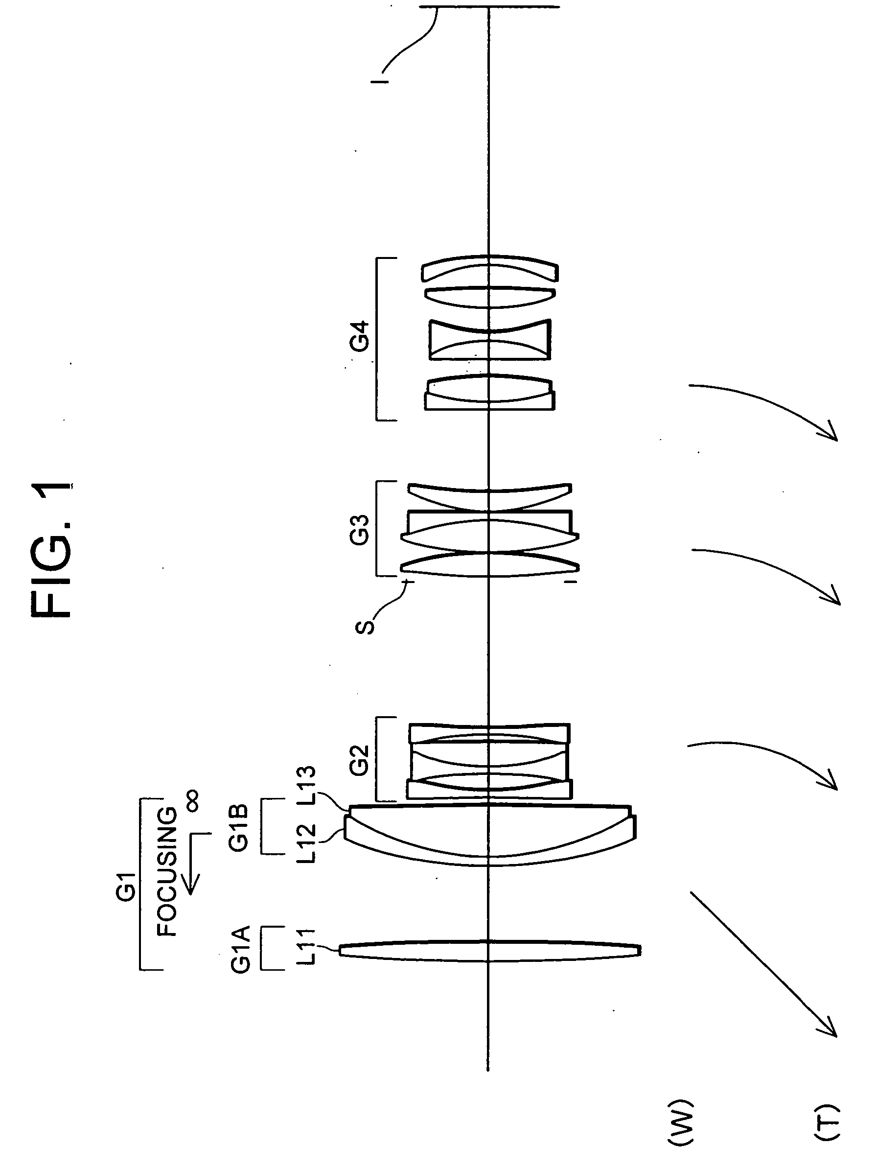
[0138]FIG. 1 is a diagram showing a sectional view of a zoom lens system according to Example 1 of a first embodiment of the present invention together with a trajectory of each lens group upon zooming. In FIG. 1, the zoom lens system is composed of, in order from an object, a first lens group G1 having positive refractive power, a second lens group G2 having negative refractive power, an aperture stop S, a third lens group G3 having positive refractive power, and a fourth lens group G4 having negative refractive power. When the state of lens group positions varies from a wide-angle end state (W) to a telephoto end state (T), the first lens group G1, the third lens group G3, and the fourth lens group G4 move to the object and the second lens group G2 moves once to the image and, then, moves to the object such that a distance between the first lens group G1 and the second lens group G2 increases, a distance between the second lens group G2 and the third lens group G3 decreases, and a...

example 2

[0149]FIG. 5 is a diagram showing a sectional view of a zoom lens system according to Example 2 of the first embodiment of the present invention together with a trajectory of each lens group upon zooming. In FIG. 5, the zoom lens system is composed of, in order from an object, a first lens group G1 having positive refractive power, a second lens group G2 having negative refractive power, an aperture stop S, a third lens group G3 having positive refractive power, and a fourth lens group G4 having negative refractive power. When the state of lens group positions varies from a wide-angle end state (W) to a telephoto end state (T), the first lens group G1, the third lens group G3, and the fourth lens group G4 move to the object and the second lens group G2 moves once to the image I and, then, moves to the object such that a distance between the first lens group G1 and the second lens group G2 increases, a distance between the second lens group G2 and the third lens group G3 decreases, a...


PUM


Abstract

Object is to provide an inner-focusing type zoom lens system carrying out focusing by moving a portion of a first lens group suitable for an auto-focus SLR camera. A zoom lens system includes, in order from an object, a first lens group having positive refractive power, a second lens group having negative refractive power, and a third lens group having positive refractive power. Upon zooming from a wide-angle end state to a telephoto end state, a distance between the first and the second lens groups increases, and a distance between the second and the third lens groups decreases. The first lens group is composed of, in order from the object, a 1A lens group G1A having positive refractive power, and a 1B lens group G1B having positive refractive power. Focusing from infinity to a close-range object is carried out by moving only the 1B lens group G1B to the object.

Description

[0001] The disclosure of the following priority applications are herein incorporated by reference: [0002] Japanese Patent Application No. 2004-099773 filed on Mar. 30, 2004, [0003] Japanese Patent Application No. 2004-105319 filed on Mar. 31, 2004, [0004] Japanese Patent Application No. 2005-036624 filed on Feb. 14, 2005 and [0005] Japanese Patent Application No. 2005-036633 filed on Feb. 14, 2005. BACKGROUND OF THE INVENTION [0006] 1. Field of the Invention [0007] The present invention relates to a zoom lens system suitable for a single-lens-reflex (SLR) camera using a silver-halide film or a solid-state imaging device and in particular to an internal-focusing zoom lens system capable of focusing by moving a portion of the optical system in a first lens group and also in particular to a compact zoom lens system having a vibration reduction function with a zoom ratio of about four and an angle of view of about 22° or more in a wide-angle end state. [0008] 2. Related Background Art [...

Claims


Application Information

Patent Timeline
Patent Type & Authority Applications(United States)
IPC IPC(8): G02B15/14G02B15/173
CPCG02B15/173G02B15/144105
Inventor SHIBAYAMA, ATSUSHIMIZUGUCHI, KEIKO
Owner NIKON CORP
Why Eureka
Try Eureka