Magnetic head structure with enlarged insulating layer

a head structure and insulating layer technology, applied in the direction of head carriers, heads with metal sheet cores, instruments, etc., can solve the problems of floating surface deformation and thermal deformation that cannot be fundamentally solved, and achieve the effect of reducing protrusion

Inactive Publication Date: 2005-10-06
TOSHIBA STORAGE DEVICE CORP
View PDF7 Cites 14 Cited by
  • Summary
  • Abstract
  • Description
  • Claims
  • Application Information

AI Technical Summary

Benefits of technology

[0018] In this arrangement, the material layer having coefficient of thermal expansion smaller than that of the protective layer suppresses the thermal expansion o

Problems solved by technology

Such thermal deformation may cause deformation of the floating surface.
However, as there is a large difference between coefficient of thermal expansion of the protective layer and that of the insulating layer, as describ

Method used


Image

  • Magnetic head structure with enlarged insulating layer
  • Magnetic head structure with enlarged insulating layer
  • Magnetic head structure with enlarged insulating layer

Examples


Embodiment Construction

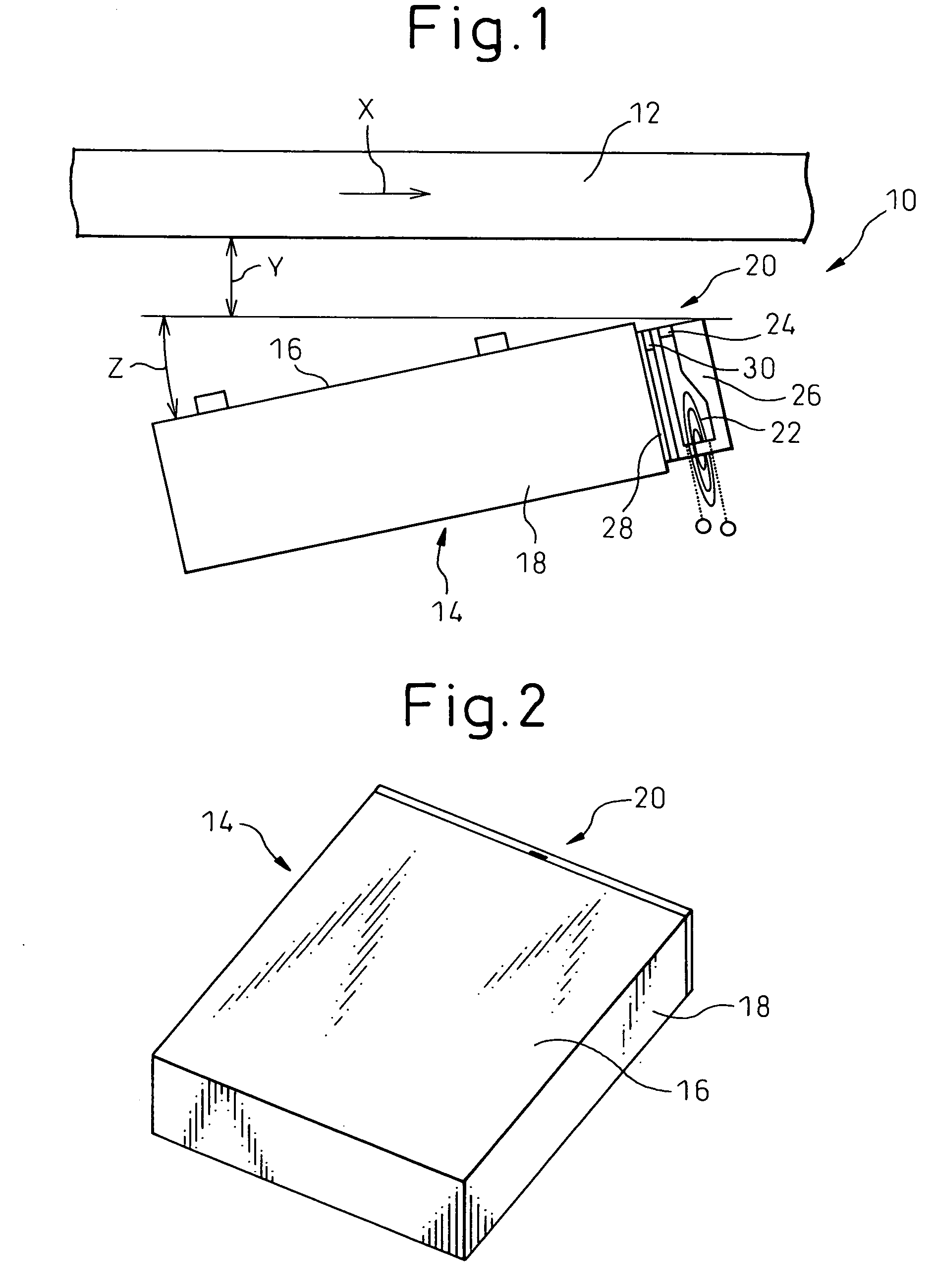
[0038] The preferred embodiment of the present invention will now be explained with reference to the accompanying drawings. FIG. 1 is a schematic view illustrating a part of a magnetic disk apparatus according to an embodiment of the present invention. FIG. 2 is a perspective view illustrating the magnetic head slider.

[0039] The magnetic disk apparatus 10 includes magnetic disks 12 and magnetic head sliders 14. The magnetic head slider 14 has a floating surface 16 and a floating rail (not shown). In operation, the disk rotates in the direction shown by the arrow X, and the magnetic head slider 14 floats with respect to the disk 14 with the floating amount Y and the pitch angle Z. The floating amount Y is approximately 10 nm, for example.

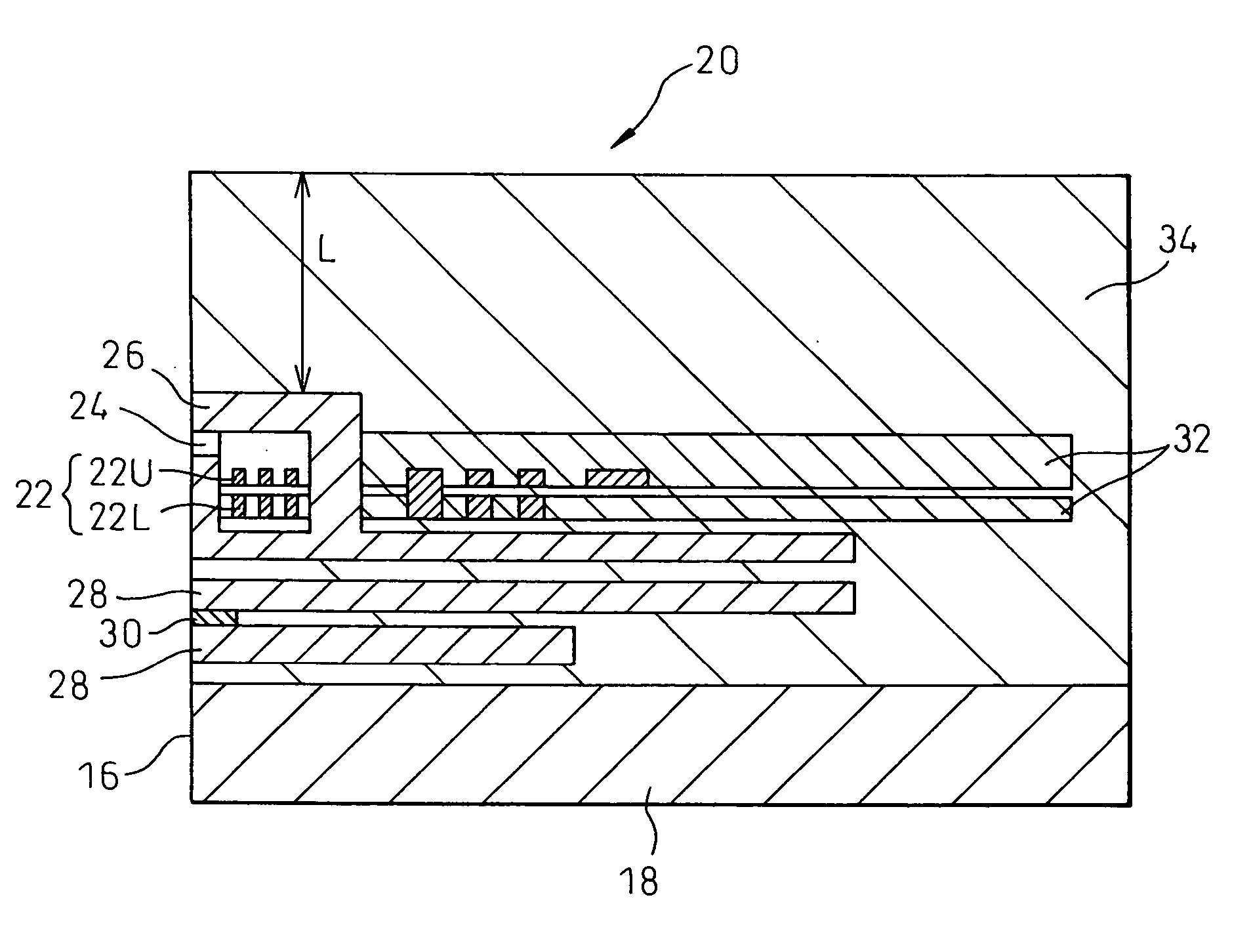
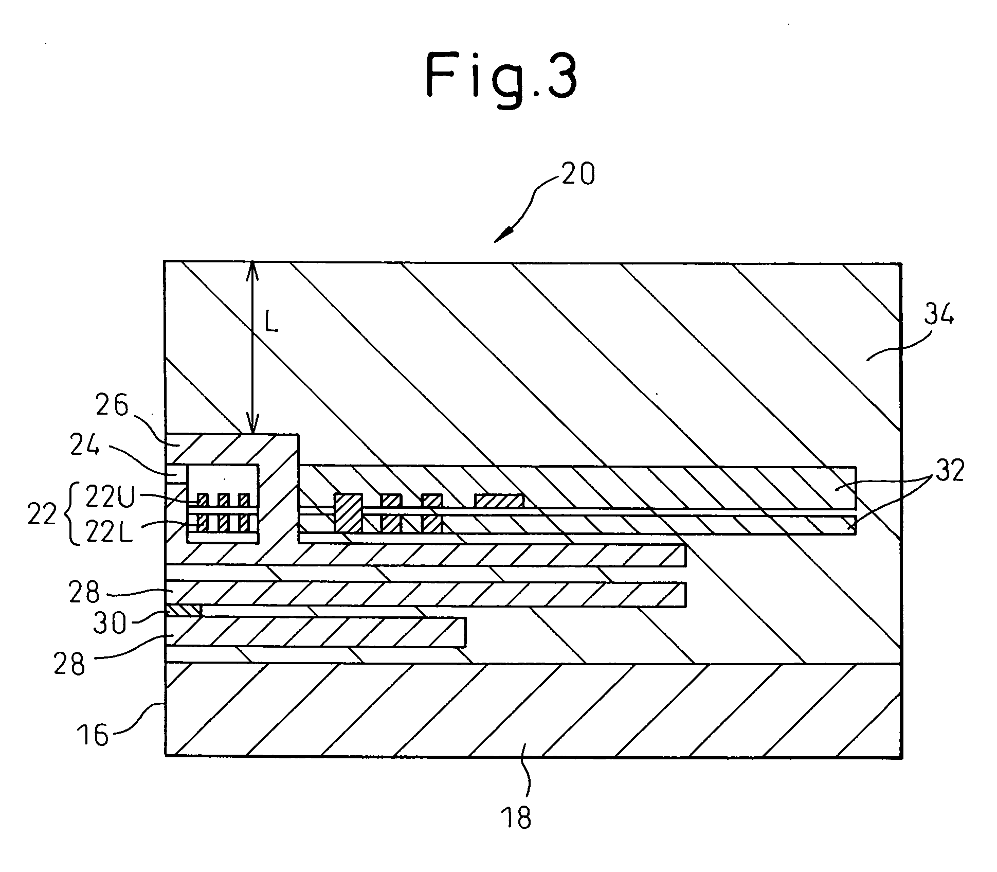
[0040] The magnetic head slider 14 comprises a substrate 18 forming a slider body and a magnetic head structure 20 provided on the substrate 18. The magnetic head structure 20 is formed by laminating thin films of several materials. The magnetic he...


PUM


Abstract

A magnetic head structure has a coil and a magnetic pole allowing a magnetic flux generated by the coil to be transmitted therethrough and forming a magnetic gap. An insulating layer surrounds the coil, and a protective layer covers the insulating layer and the magnetic pole. The insulating layer has a volume equal to or greater than a value which is determined with respect to a thickness of the protective layer. It is preferable to increase the volume of the insulating layer as the thickness of the protective layer is made greater. By increasing the volume of the insulating layer, the protrusion of a portion of a floating surface of the magnetic head slider near the magnetic pole, toward the disk, is reduced.

Description

BACKGROUND OF THE INVENTION [0001] 1. Field of the Invention [0002] The present invention relates to a magnetic head structure. [0003] 2. Description of the Related Art [0004] A magnetic disk apparatus includes a plurality of disks and a plurality of magnetic head structures arranged between the disks. The magnetic head structure is arranged in a magnetic head slider. The surface of the magnetic head slider facing the disk is called a floating surface. The magnetic head structure comprises a coil, a magnetic pole allowing a magnetic flux generated by the coil to be transmitted therethrough and forming a magnetic gap, an insulating layer surrounding the coil, and a protective layer covering the insulating layer and the magnetic pole, with these members being provided on a substrate forming the magnetic head slider. Also, a shield and a reading element (MR element) are arranged on the substrate. [0005] When data are written into the disk, an electric current is supplied to the coil. T...

Claims


Application Information

Patent Timeline
IPC IPC(8): G11B5/127G11B5/17G11B5/31G11B5/60
CPCG11B5/127G11B5/17G11B5/3106G11B5/6005G11B5/3133G11B5/3136G11B5/3123G11B5/31
Inventor AOKI, KENICHIROHOSHINO, TOSHINORINAKADA, TOSHIYUKIARUGA, KEIJIMAEDA, HIROSHI
Owner TOSHIBA STORAGE DEVICE CORP
Why Eureka
Try Eureka