Interior illuminator for automobile

a technology for interior illumination and automobiles, applied in the direction of building locks, signalling/lighting devices, and compartment lighting, can solve the problem of insufficient quantity of light at the other end, and achieve the effect of reducing the weight of the housing, increasing internal reflection, and reducing the material cost of the housing

Inactive Publication Date: 2005-10-06
HONDA ACCESS CORP
View PDF1 Cites 17 Cited by
  • Summary
  • Abstract
  • Description
  • Claims
  • Application Information

AI Technical Summary

Benefits of technology

[0014] Furthermore, since the base end through-holes and the curved through-hole are provided, the ease of molding can be maintained even through the engaging protrusions and the engaging step section are formed in shaping of the resin into the housing. Furthermore, since the base end through-holes and the curved through-hole are provided, the material cost for the housing can be reduced, and the weight of the housing can be reduced.
[0015] Furthermore, the base end through-holes and the curved through-hole serve to diffuse the light launched into the light guide body by the light emitting elements uniformly over the length of the light guide body. When the light from the light emitting elements is launched into the light guide body held in the shape of the letter U, the quantity of diffused light is large in the vicinities of the insertion holes in the straight holding sections of the light guide body, which are adjacent to the positions where the light is launched by the light emitting elements, and in the arc-shaped holding section of the light guide body, which provides increased internal reflection, and the quantity of diffused light is small in parts of the light guide body which are held in the straight holding sections distant from the insertion holes. Thus, according to the present invention, the base end through-holes and the curved through-hole are provided at the positions in the light guide body where the quantity of diffused light is large, thereby directing some of the diffused light in the light guide body to the inside of the housing, thereby controlling an excessive quantity of diffused light. Thus, the quantity of light can be made substantially uniform over the light guide body.
[0016] Here, it is preferable that the light emitting elements and the light emitting element control unit are provided integrally on a planar substrate, and the substrate is connected to the housing at a position at outer end of the arc-shaped holding section of the light guide holding groove and at a positi

Problems solved by technology

Furthermore, since the paired light emitting elements launch light into the ends of the light guide body, a sufficient quantity of light can be achieved over the leng

Method used


Image

  • Interior illuminator for automobile
  • Interior illuminator for automobile
  • Interior illuminator for automobile

Examples


Embodiment Construction

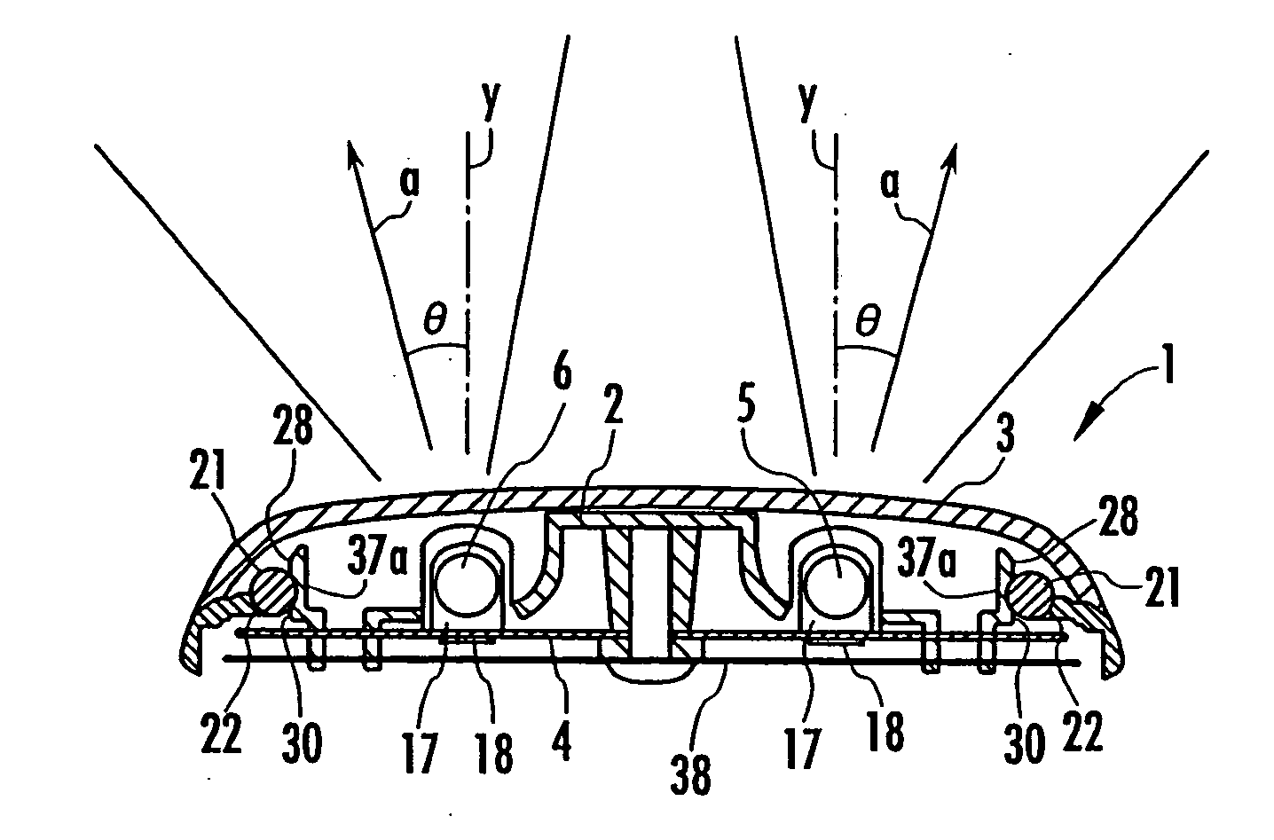
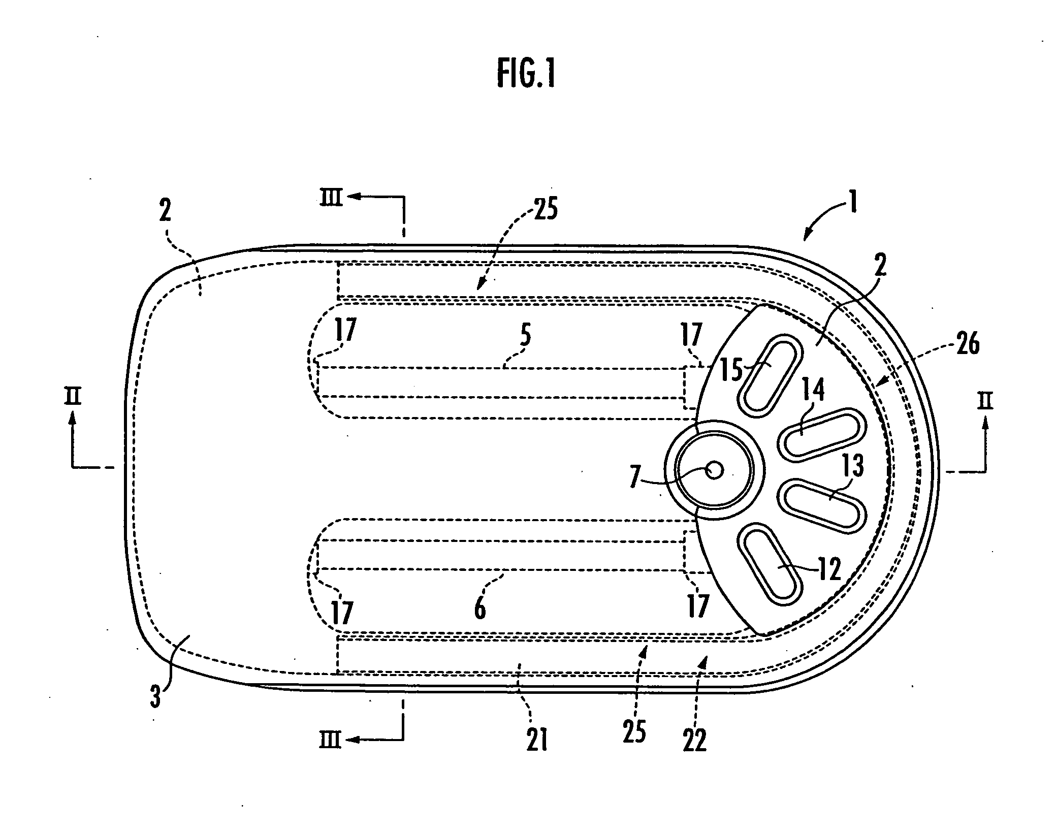
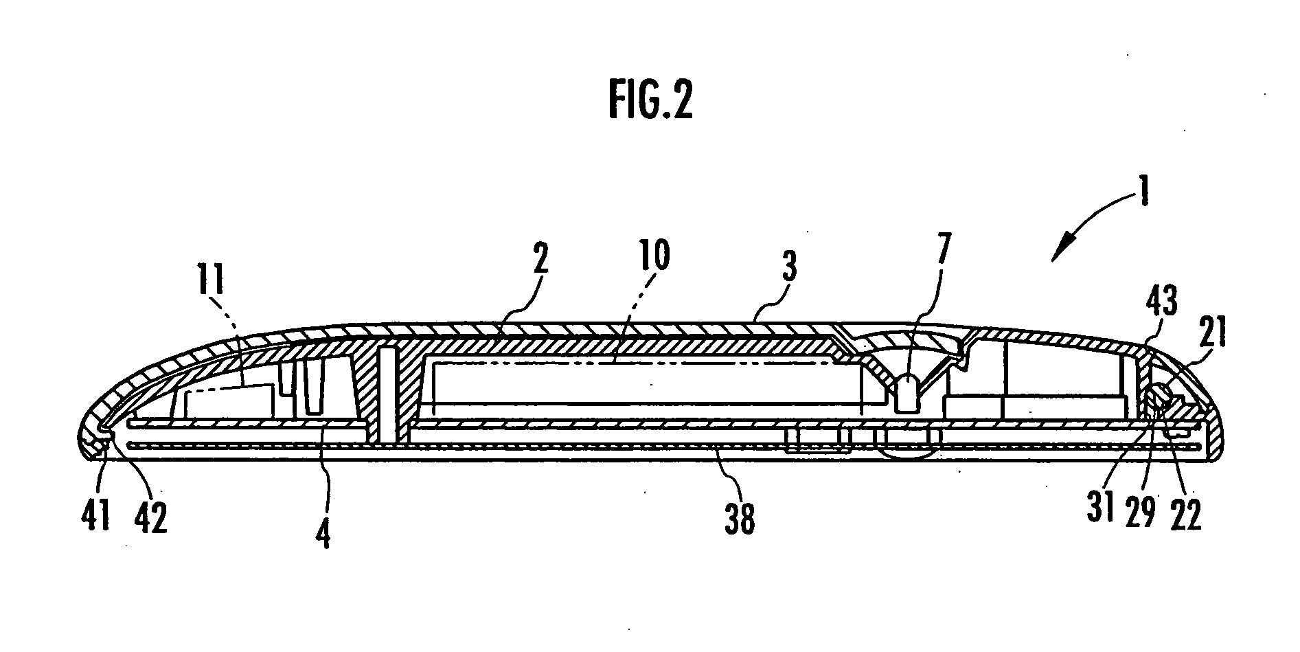
[0036] An embodiment of the present invention will be described with reference to the drawings. FIG. 1 is a plan view of an illuminator according to this embodiment, FIG. 2 is a cross sectional view of the illuminator taken along the line II-II in FIG. 1, FIG. 3 is a cross sectional view of the illuminator taken along the line III-III in FIG. 1, FIG. 4 is a plan view of a circuit board, FIG. 5 is a cross sectional view of a part of the circuit board, FIG. 6 is a plan view of a housing, FIG. 7 is a cross sectional view of the housing taken along the line VII-VII in FIG. 6, FIG. 8 is a cross sectional view of the housing being formed taken along the line VIII-VIII in FIG. 6, FIG. 9 is a cross sectional view of the housing being formed taken along the line IX-IX in FIG. 6, FIG. 10 is an exploded perspective view of the illuminator according to this embodiment, FIG. 11 is a plan view of an optically transparent cover, FIG. 12 is a cross sectional view of the illuminator attached to the ...


PUM


Abstract

To provide an interior illuminator for an automobile that can produce a decorative effect by illumination in addition to illuminating the interior of the automobile and has a simple structure and a small size. A secondary light emitting unit is provided around primary light emitting units 5 and 6 for illuminating the interior of the automobile. A housing 2 that holds the primary light emitting units 5, 6 and the secondary light emitting unit is provided. The secondary light emitting unit has a U-shaped light guide body 21, light emitting elements 8 and 9 for launching light into the light guide body at the ends thereof, and a light emitting element control unit 11 for controlling the light emitting elements 8 and 9. The housing 2 has a light guide body holding groove that holds the light guide body 21, insertion holes for introducing the light guide body into the housing at the ends of the light guide body holding groove, and a housing section that houses the light emitting element and the light emitting element control unit.

Description

BACKGROUND OF THE INVENTION [0001] 1. Field of the Invention [0002] The present invention relates to an interior illuminator for an automobile which is provided on the ceiling of the automobile and illuminates the interior of the automobile. [0003] 2. Description of the Related Art [0004] Conventional known illuminators for illuminating the interior of an automobile include one using a plurality of lamps as a light source (see Japanese Patent Laid-Open No. 2000-177482) and one using a fluorescent lamp as a light source (see Japanese Patent Laid-Open No. 10-129345). [0005] As for the automobile, the recent trend is toward a wider interior space and a higher riding capacity, and it is desired that the illumination produces a decorative effect for occupants on the backseat. However, conventional illuminators are designed primarily for interior illumination and emit relatively intense light, and therefore, there is a problem that an atmosphere desired by an occupant cannot be easily pro...

Claims


Application Information

Patent Timeline
IPC IPC(8): B60Q3/00B60Q3/02F21S8/10F21V8/00G01D5/34
CPCB60Q3/004B60Q3/0203G01D5/34B60Q3/0293B60Q3/0279B60Q3/74B60Q3/51B60Q3/64B60Q3/80B60Q2500/30
Inventor IWAI, SHIRO
Owner HONDA ACCESS CORP
Why Eureka
Try Eureka