
Closed automatic fluid mixing system

a technology of automatic fluid mixing and closed fluid, which is applied in the direction of transportation and packaging, process and machine control, instruments, etc., can solve the problems of occupying a site that is literally and/or figuratively costly, presenting many problems, and consuming a lot of resources

Inactive Publication Date: 2005-10-06
BJ SERVICES CO
View PDF10 Cites 32 Cited by
  • Summary
  • Abstract
  • Description
  • Claims
  • Application Information

AI Technical Summary

Benefits of technology

[0008] A closed automatic fluid mixing apparatus and method for mixing two fluids while maintaining a feed pressure of the mixed fluid at a predetermined level are disclosed. The apparatus comprises a first fluid feed, a second fluid feed, a mixing valve, and a closed control system. The mixing valve is capable of mixing a first fluid received from the first fluid feed and a second fluid received from the second fluid feed to produce a mixed fluid. The closed control system is capable of controlling the mixing valv

Problems solved by technology

Although this system has worked satisfactorily for many years, it presents many problems.
The mixing tanks can be relatively expensive—up to $50,000 each—and can occupy space at the site that is literally and / or figuratively costly.
The fluids are frequently highly acidic, and so the mixing tank sometimes creates environmental and safety concerns.
For instance, if a job is cut short, the mixed fluid remaining in the mixing tank must be disposed of, which may implicate compliance with environmental regulations in some circumstances.
These drawbacks are tolerated, however, because of the needs of the positive displacement pump.
If the supply of fluid to the pump is interrupted, the pump will “cavitate.” Persistent cavitation can produce effects in the pump that can damage or even destroy the pump.

Method used


Image

  • Closed automatic fluid mixing system
  • Closed automatic fluid mixing system
  • Closed automatic fluid mixing system

Examples


Embodiment Construction

[0014] Illustrative embodiments of the invention are described below. In the interest of clarity, not all features of an actual implementation are described in this specification. It will of course be appreciated that in the development of any such actual embodiment, numerous implementation-specific decisions must be made to achieve the developers' specific goals, such as compliance with system-related and business-related constraints, which will vary from one implementation to another. Moreover, it will be appreciated that such a development effort, even if complex and time-consuming, would be a routine undertaking for those of ordinary skill in the art having the benefit of this disclosure.

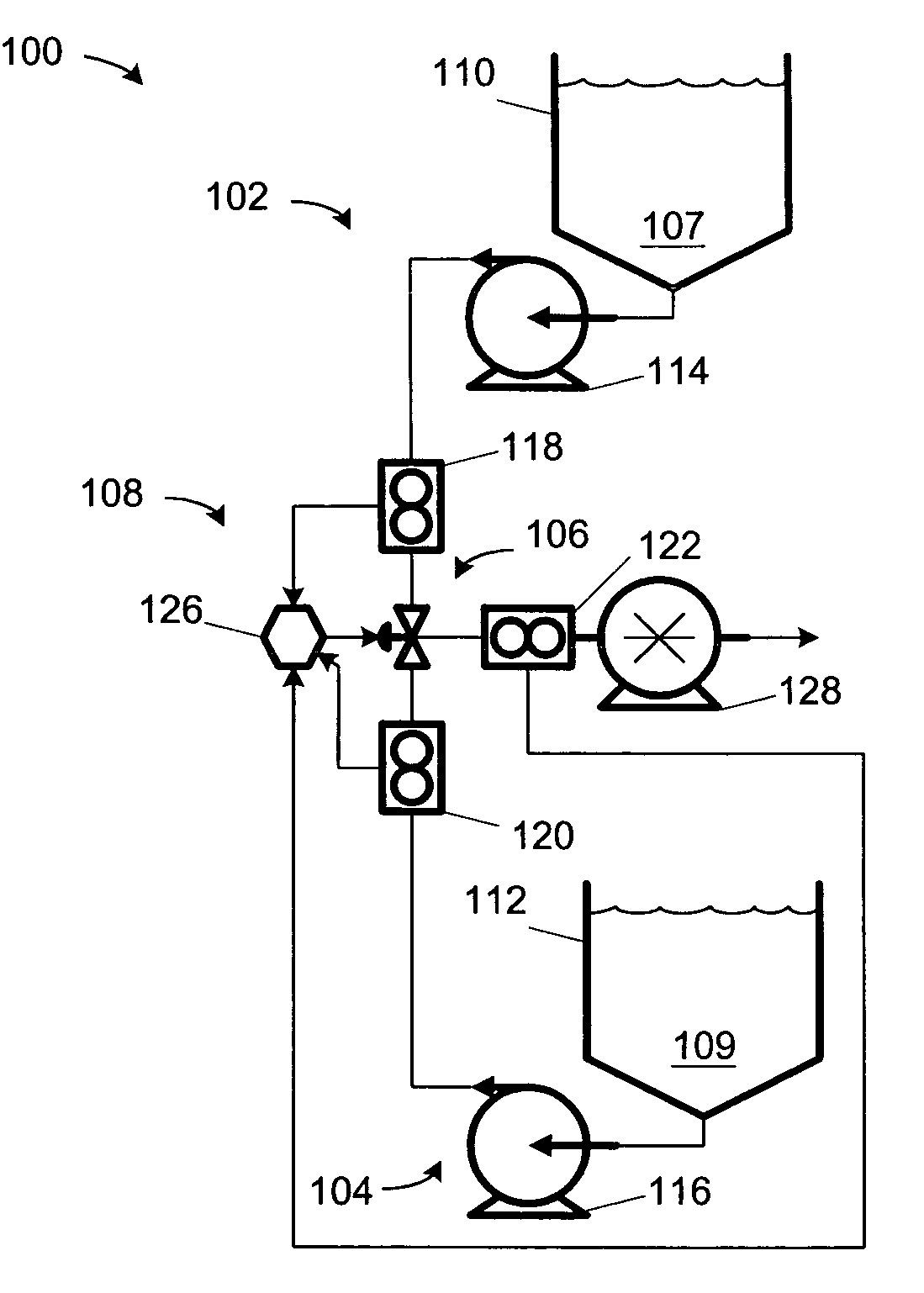
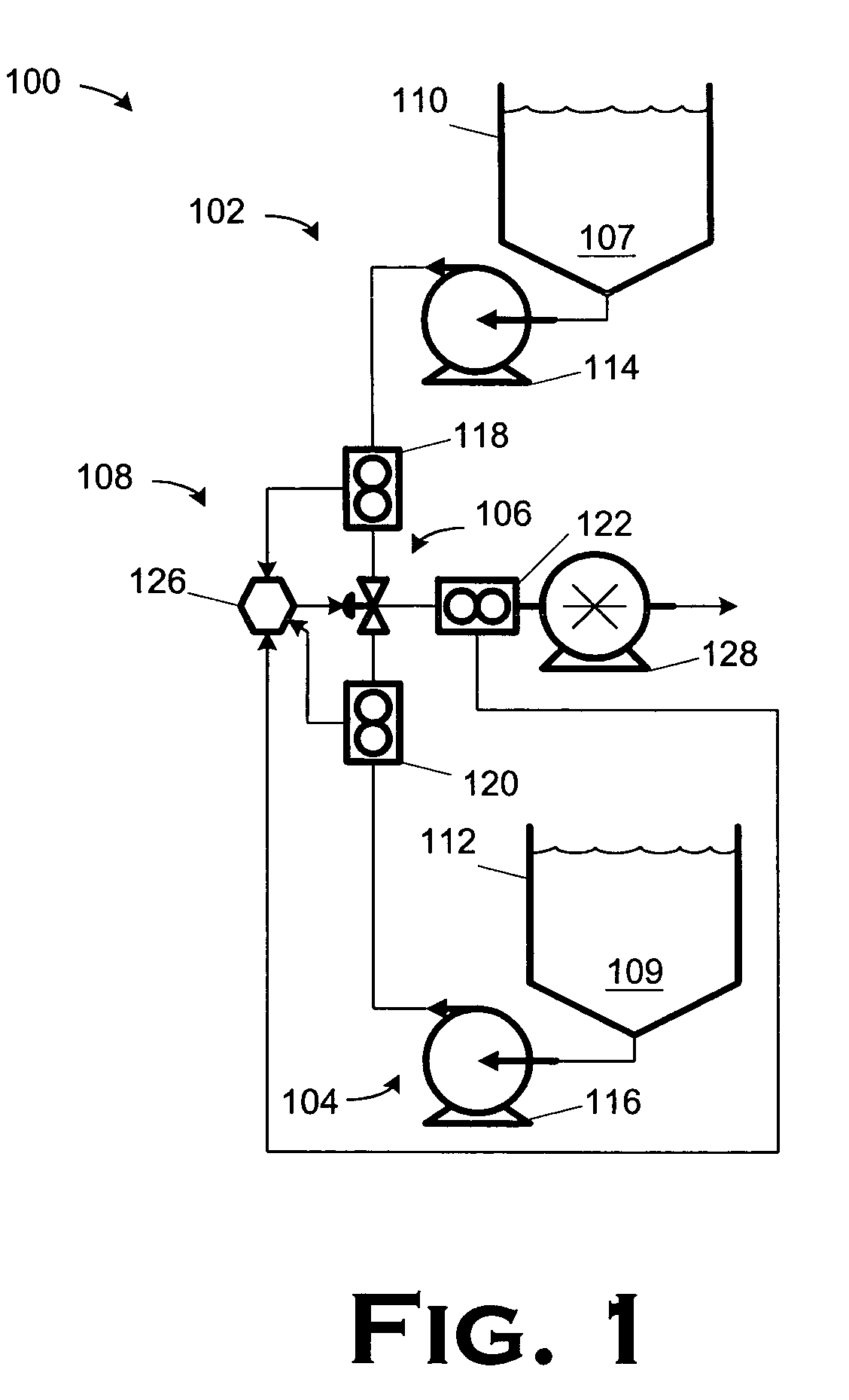
[0015]FIG. 1 illustrates a mixing apparatus 100 constructed and operated in accordance with one particular embodiment of the present invention. The apparatus 100 includes a first fluid feed 102, a second fluid feed 104, a mixing valve 106, and a closed control system 108. The mixing valve 106 i...


PUM


Abstract

A closed automatic fluid mixing apparatus and method for mixing two fluids while maintaining a feed pressure of the mixed fluid at a predetermined level are disclosed. The apparatus comprises a first fluid feed, a second fluid feed, a mixing valve, and a closed control system. The mixing valve is capable of mixing a first fluid received from the first fluid feed and a second fluid received from the second fluid feed to produce a mixed fluid. The closed control system is capable of controlling the mixing valve to determine the ratio of the first and second fluids in the mixed fluid while maintaining the pressure of the mixed fluid at a predetermined level. The method comprises feeding a first fluid and a second fluid to a mixing valve; mixing the first and second fluids therein; and controlling the mixing valve's actuation of to determine the ratio of the first and second fluids in a resultant mixed fluid while maintaining the pressure of the mixed fluid at a predetermined level.

Description

BACKGROUND OF THE INVENTION [0001] 1. Field of the Invention [0002] The present invention pertains to a closed automatic fluid mixing system, and, more particularly, to a closed automatic fluid mixing system capable of mixing two fluids while maintaining a feed pressure of the mixed fluid at a predetermined level. [0003] 2. Description of the Related Art [0004] Wells drilled in exploration or for production of hydrocarbons typically employ fluids pumped at relatively high pressures down the bore of the well. A variety of fluids are used for a variety of purposes. The fluids will frequently comprise several components that are mixed at the site of the well. The component fluids are typically transported to the site and stored in separate holding tanks. The component fluids are then fed into a mixing tank, where they are mixed in the desired ratio for the anticipated application. The mixed fluid is then fed to a positive displacement pump, which pumps the fluid down the well bore. Pos...

Claims


Application Information

Patent Timeline
IPC IPC(8): B01F5/00B01F15/04G05D11/13
CPCB01F5/0077G05D11/132B01F15/0429B01F25/105B01F35/833
Inventor KELLEY, MILTON I.BURNETTE, BLAKE C.CARLSON, BRADLEY T.
Owner BJ SERVICES CO
Learn More