
Method and apparatus for effectively compressing motion vectors in multi-layer structure

a multi-layer structure and motion vector technology, applied in the field of video compression method, can solve the problems of negative influence on compression performance, inability to meet various requirements of consumers, existing text-based communication methods, etc., and achieve the effect of effective prediction of motion vector

Inactive Publication Date: 2005-10-06
SAMSUNG ELECTRONICS CO LTD
View PDF6 Cites 89 Cited by
  • Summary
  • Abstract
  • Description
  • Claims
  • Application Information

AI Technical Summary

Benefits of technology

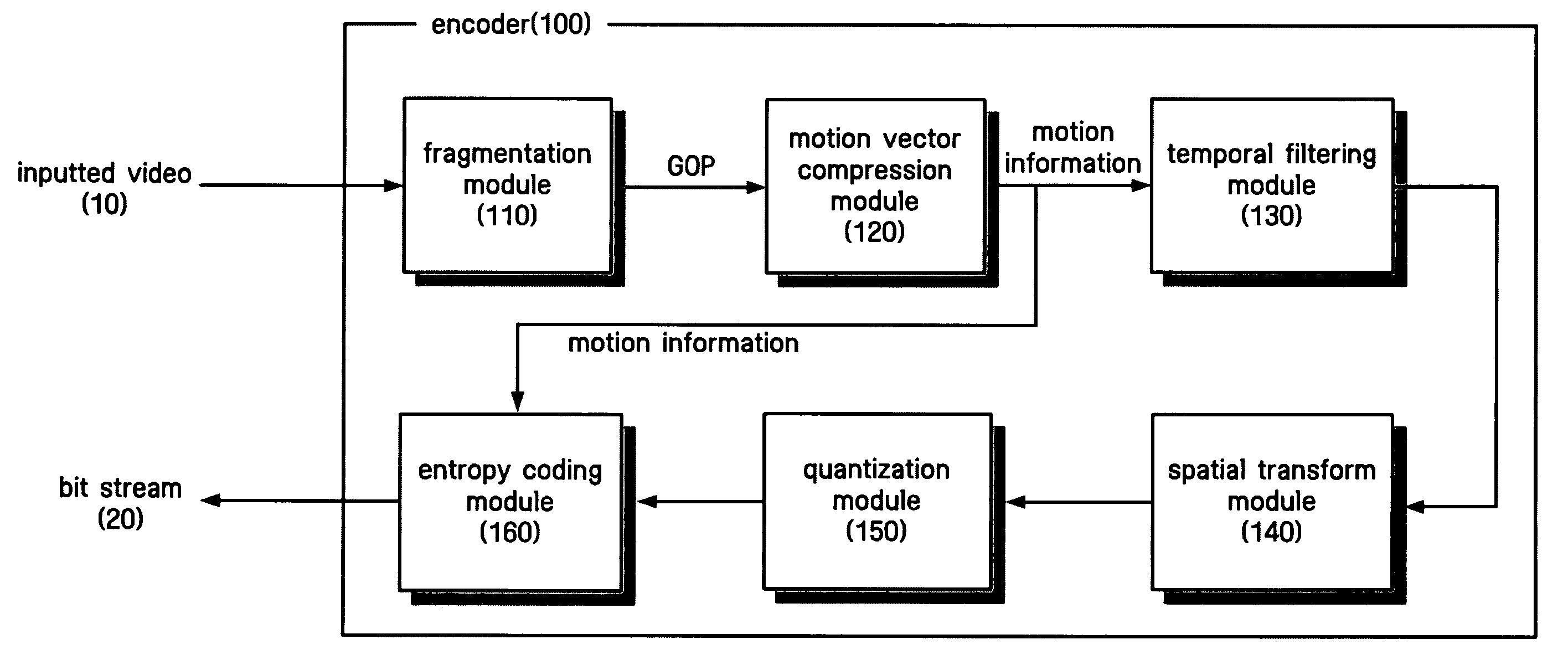
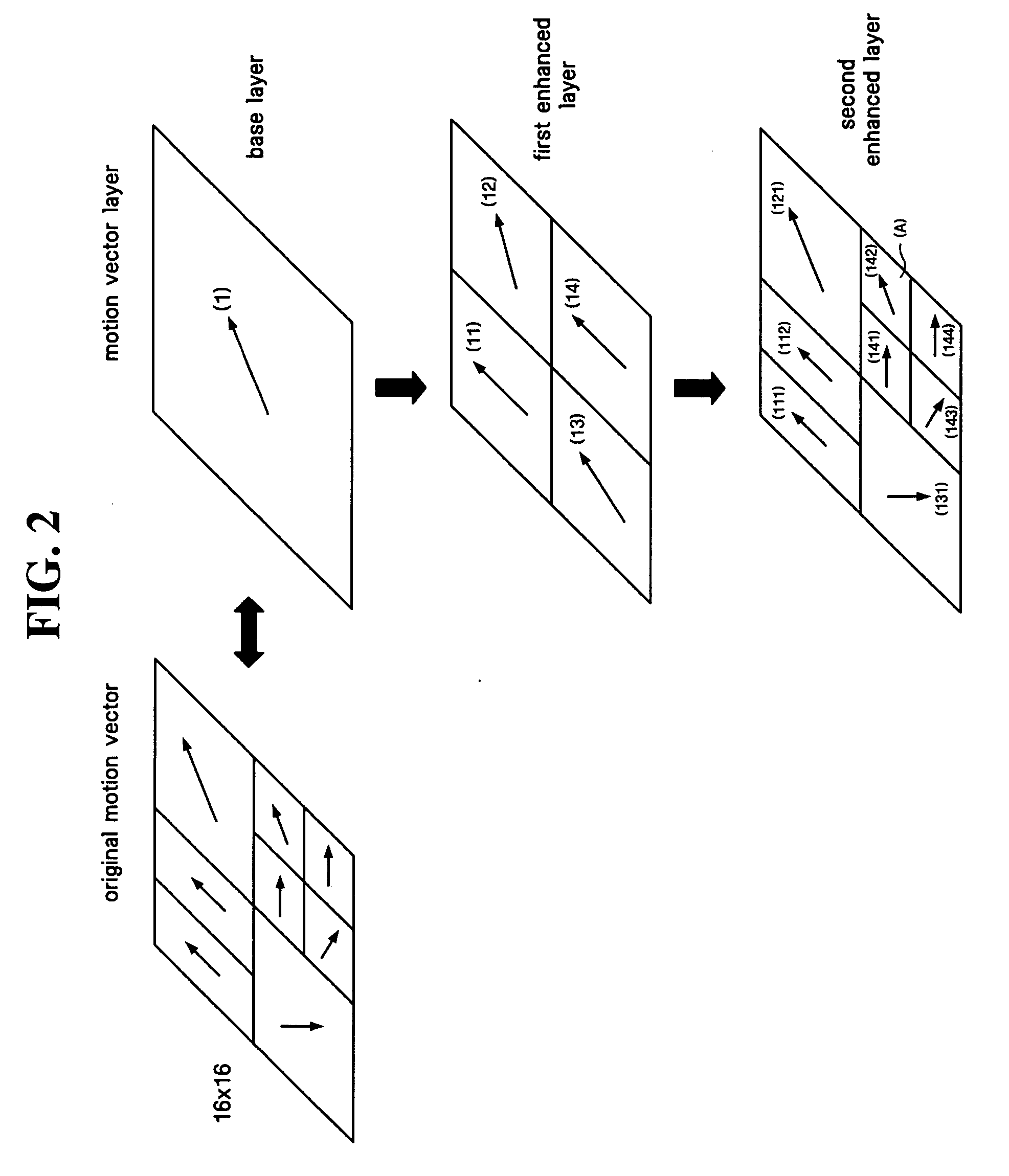
The present invention provides a method for effectively predicting the motion vector of an enhanced layer in a multi-layer structure video encoder. The method takes into account the motion vectors of both the base layer and the enhanced layer when predicting the motion vector of the enhanced layer. The method also considers the motion vectors of blocks around the block in which the motion vector is predicted. The invention also includes a motion vector compression apparatus and a video decoder that support a motion vector of a multi-layer structure. The technical effects of the invention include improved video compression and reduced temporal and spatial redundancy in video data.

Problems solved by technology

The existing text-based communication method cannot satisfy various requirements of a consumer.
Further, since multimedia data are of large quantities, a large capacity of storage medium and a wide transmission bandwidth are required for such data.
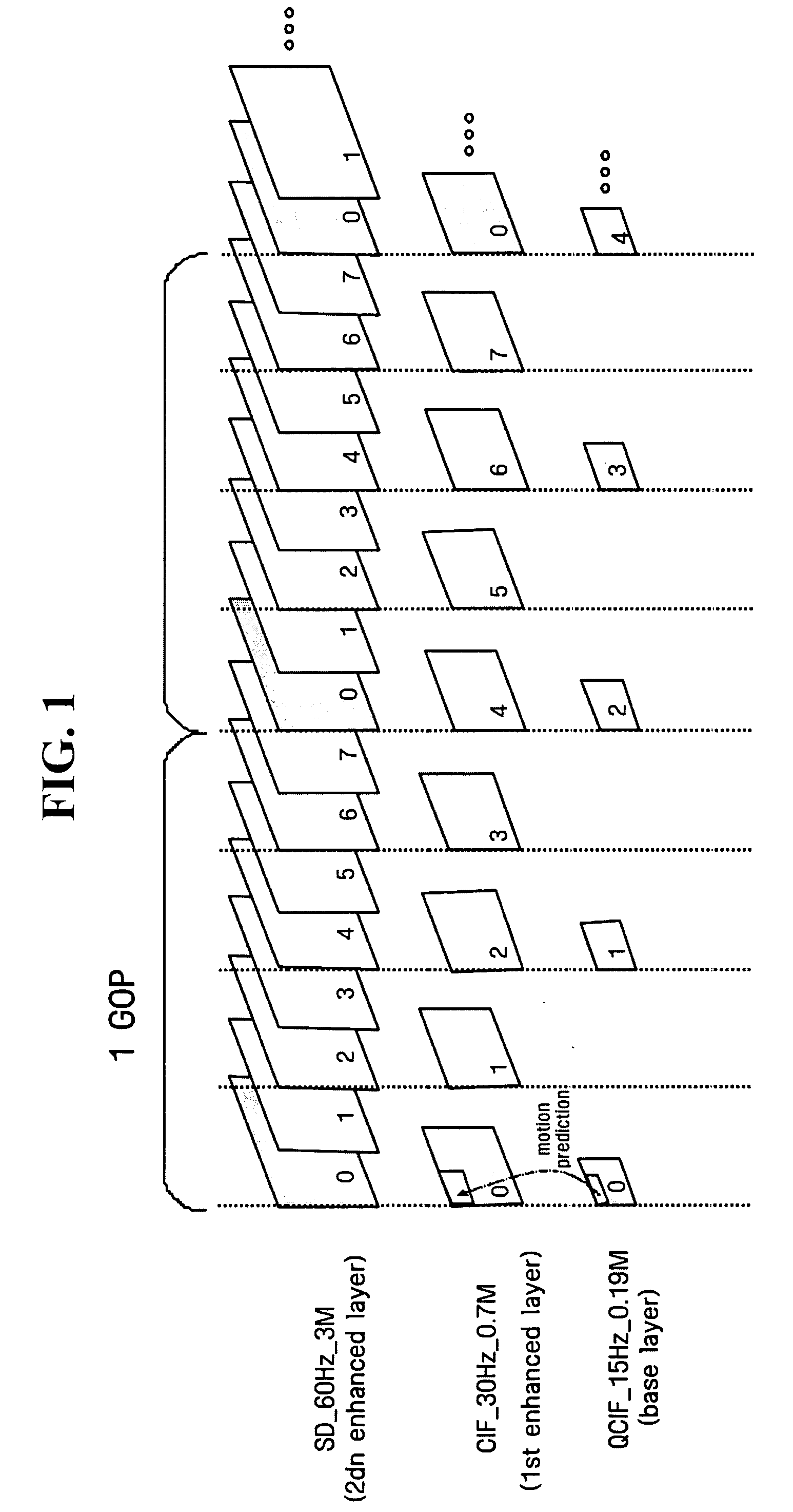
However, the conventional method does not use correlation with adjacent motion vectors, simply obtains only difference with a motion vector of a lower layer, and encodes the obtained difference.
Accordingly, a prediction is not performed well, and thus difference of a motion vector in an enhanced layer increases, thereby having a negative influence on compression performance.

Method used


Image

  • Method and apparatus for effectively compressing motion vectors in multi-layer structure
  • Method and apparatus for effectively compressing motion vectors in multi-layer structure
  • Method and apparatus for effectively compressing motion vectors in multi-layer structure

Examples


Embodiment Construction

[0064] Hereinafter, embodiments of the present invention will be described in detail with reference to the accompanying drawings.

[0065] Advantages and features of the present invention, and methods for achieving them will be apparent to those skilled in the art from the detailed description of the embodiments together with the accompanying drawings. However, the scope of the present invention is not limited to the embodiments disclosed in the specification, and the present invention can be realized in various types. The described present embodiments are presented only for completely disclosing the present invention and helping those skilled in the art to completely understand the scope of the present invention, and the present invention is defined only by the scope of the claims. Additionally, the same reference numerals are used to designate the same elements throughout the specification and drawings.

[0066] Hereinafter, an entire construction of a video / image coding system will b...


PUM


Abstract

A method and an apparatus for elevating compression efficiency of a motion vector by effectively predicting a motion vector of an enhanced layer by means of a motion vector of a base layer in a video coding method employing a multi-layer structure are disclosed. A motion vector compression apparatus includes: a down-sampling module for down-sampling an original frame to have a size of a frame in each layer; a motion vector search module for obtaining a motion vector in which an error or a cost function is minimized with respect to the down-sampled frame; a reference vector generation module for generating a reference motion vector in a predetermined enhanced layer by means of a block of a lower layer corresponding to a predetermined block in the predetermined enhanced layer, and motion vectors in blocks around the block; and a motion difference module for calculating a difference between the obtained motion vector and the reference motion vector.

Description

CROSS-REFERENCE TO RELATED APPLICATIONS [0001] This application claims priority from Korean Patent Application No. 10-2004-0026778 filed on Apr. 19, 2004 in the Korean Intellectual Property Office, and U.S. Provisional Patent Application No. 60 / 557,709 filed on Mar. 31, 2004 in the United States Patent and Trademark Office, the disclosures of which are incorporated herein by reference in their entirety.BACKGROUND OF THE INVENTION [0002] 1. Field of the Invention [0003] The present invention relates to a video compression method, and more particularly to a method and an apparatus for elevating compression efficiency of a motion vector (MV) by effectively predicting a motion vector of an enhanced layer by means of a motion vector of a base layer in a video coding method employing a multi-layer structure. [0004] 2. Description of the Prior Art [0005] With the development of technology of information and communication including the Internet, image communication as well as text and voice...

Claims


Application Information

Patent Timeline
Patent Type & Authority Applications(United States)
IPC IPC(8): H04N7/12H04N7/32H04N7/26
CPCH04N19/53H04N19/52G09F13/18G09F2013/227G09F2013/1881G09F2013/1877G09F2013/1859
Inventor HA, HO-JINCHA, SANG-CHANGHAN, WOO-JIN
Owner SAMSUNG ELECTRONICS CO LTD
Learn More