Spallation device for producing neutrons

a technology of a spallation device and a neutron, which is applied in the direction of nuclear energy generation, nuclear reactors, electrical apparatus, etc., can solve the problems of limiting the performance of the spallation target, threatening confinement, and difficult if not impossibl

Inactive Publication Date: 2005-10-06
COMMISSARIAT A LENERGIE ATOMIQUE ET AUX ENERGIES ALTERNATIVES
View PDF14 Cites 9 Cited by
  • Summary
  • Abstract
  • Description
  • Claims
  • Application Information

AI Technical Summary

Problems solved by technology

This is very difficult if not impossible when the medium surrounding the spallation target has a fast neutron, spectrum.
Consequently, there is a hot point on the leak tight partition that limits the performances of the spallation target and can threaten confinement.
Like all elements placed on the centre line of the beam, this grid is affected by irradiation from this beam and its mechanical and thermal performances deteriorate during time.
However, this grid does not contribute to spallation and its volume is such that if any damage occurs, this grid will in turn damage or even destroy the spallation target, particularly by partial or total closing off of heat transporting fluid circuits.

Method used


Image

  • Spallation device for producing neutrons
  • Spallation device for producing neutrons
  • Spallation device for producing neutrons

Examples


Embodiment Construction

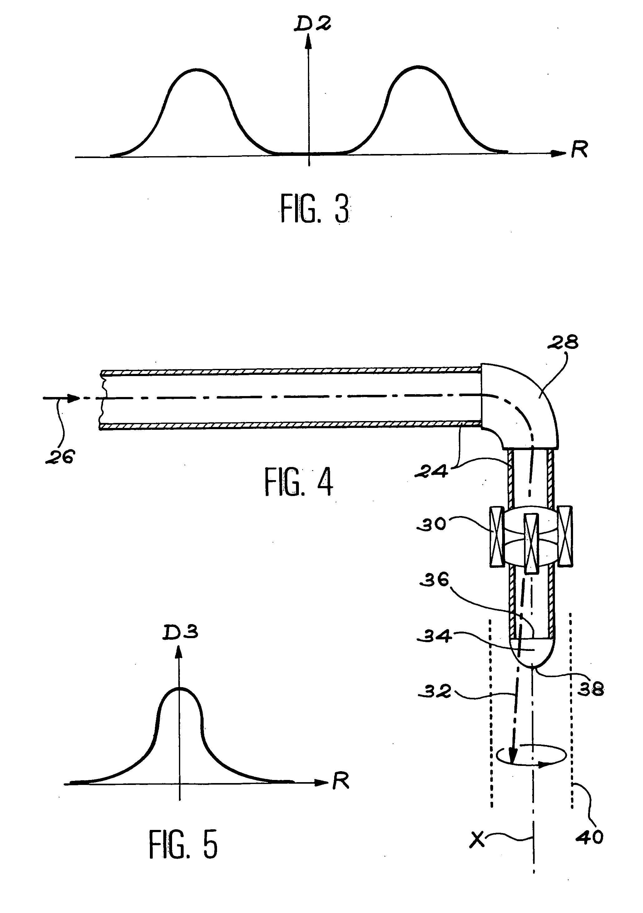
[0067] In the examples of the invention described below, a hollow particle beam also called an “annular particle beam” is used, in which the radial current density distribution is approximately gaussian. FIG. 3 diagrammatically illustrates variations of this density D2 as a function of the distance R from the hollow beam.

[0068] This is a means of solving the following two problems: [0069] limiting the current density gradient to avoid excessive internal mechanical stresses in key components of the spallation device, and particularly the leak tight partition, and the spallation target in the case of a solid target, and [0070] moving the peak power away from the axis of symmetry of the target to avoid cooling problems.

[0071] An annular distribution of the current density in the particle beam can be obtained using magnetic optical means that are placed on the input side of the leak tight partition.

[0072]FIG. 4 diagrammatically illustrates the generation of a hollow particle beam. FI...


PUM


Abstract

A spallation device for production of neutrons includes a solid spallation target that produces neutrons by interaction with a hollow particle beam propagating within a first chamber, a second chamber containing the spallation target, and a leak tight partition separating the first and second chambers.

Description

TECHNICAL FIELD [0001] This invention relates to a spallation device for the production of neutrons. [0002] The device is used in applications in all fields in which an intense neutron source is necessary. [0003] The invention is particularly applicable to basic physics, medicine and transmutation of material. STATE OF PRIOR ART [0004] Note that spallation corresponds to the interaction of particles, and particularly protons, output from an accelerator and with the high energy equal to about 200 MeV or more, with nuclei of a target. [0005] This interaction produces neutrons, for example about 30 neutrons per 1 GeV incident proton when the target is made of liquid lead. About 80% of these neutrons originate from evaporation and the remainder originate from inter-nuclear cascades. The spectrum of these neutrons has a peak at about 3.5 MeV. [0006] A spallation target may be solid, or it may be liquid. It may also be thick or thin. [0007] A liquid spallation target forms its own heat tr...

Claims


Application Information

Patent Timeline
Patent Type & Authority Applications(United States)
IPC IPC(8): G21C1/30G21K5/02G21K5/08H05H3/06H05H6/00
CPCG21C1/30G21Y2002/304Y02E30/40H05H3/06H05H6/00G21Y2004/30G21G4/02Y02E30/30
Inventor RITTER, GUILLAUME
Owner COMMISSARIAT A LENERGIE ATOMIQUE ET AUX ENERGIES ALTERNATIVES
Why Eureka
Try Eureka