Image generation apparatus, image generation system and image synthesis method

a technology of image generation and apparatus, applied in the field of surveillance camera system and surveillance camera image display method, can solve the problems of inability to provide any feasible solutions, incongruity or mismatch, and the risk of judgment error, and achieve the effect of facilitating mutual relationship and recognizing and grasping

Inactive Publication Date: 2005-10-06
HITACHI LTD
View PDF6 Cites 54 Cited by
  • Summary
  • Abstract
  • Description
  • Claims
  • Application Information

AI Technical Summary

Benefits of technology

[0011] The system is such that respective scene images, which are acquired or captured by several imaging units being different from each other in imaging direction and imaging position plus imaging view angle, are each deformed by the image deformation unit in such a way that the visual appearance of a specific region within the image of interest is matched with the same geometric shape as its corresponding region within the map whereas the partial image extraction unit extracts a specific region of the deformed image while the image synthesis / display unit synthesizes for display this extracted partial image into its corresponding region within the map. Thus, it is no longer required for operators to perform the reading and understanding of images while taking into consideration the individual imaging unit's image acquisition conditions. Simultaneously, it is also possible to readily recognize and grasp the mutual relationship of imaging ranges of respective images within the map.
[0012] According to this invention, it becomes possible to readily obtain the mutual relationship of a plurality of images on the map.

Problems solved by technology

This would cause problems, such as a risk that he or she is likely to commit judgment mistakes.
In addition, in cases where an increased number of obstructions such as public buildings or else are present in the surveillance range, the inconsistency or mismatch in geometric relationship between the surveillance camera-captured image and the map information can sometimes take place in a way depending upon the conversion processing to be performed during visual reconstruction into a single image.
Additionally, in the case of such mismatch of the geometric relationship between images captured by a plurality of cameras from different positions, the above-identified Japanese patent documents fail to provide any feasible solutions thereto.

Method used


Image

  • Image generation apparatus, image generation system and image synthesis method
  • Image generation apparatus, image generation system and image synthesis method
  • Image generation apparatus, image generation system and image synthesis method

Examples


embodiment 1

[Embodiment 1]

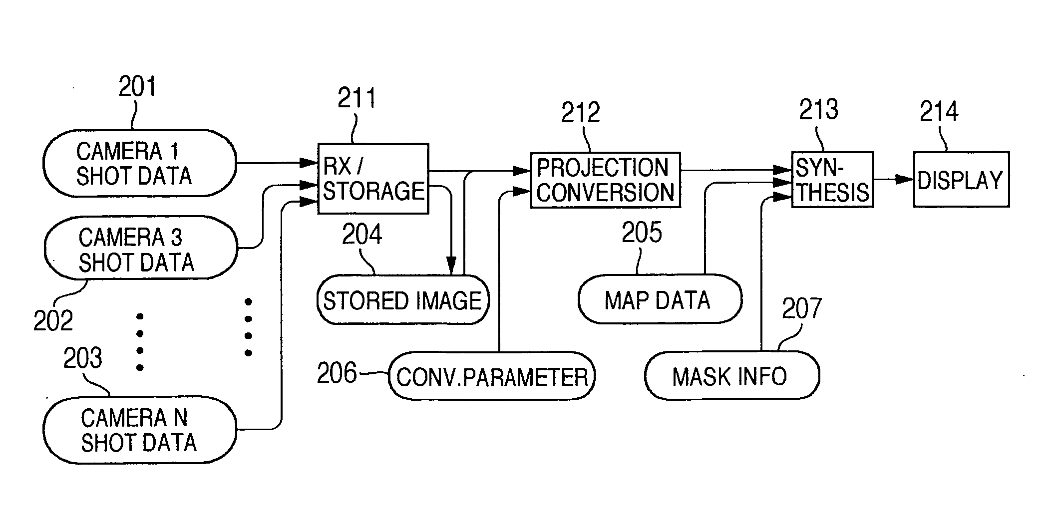
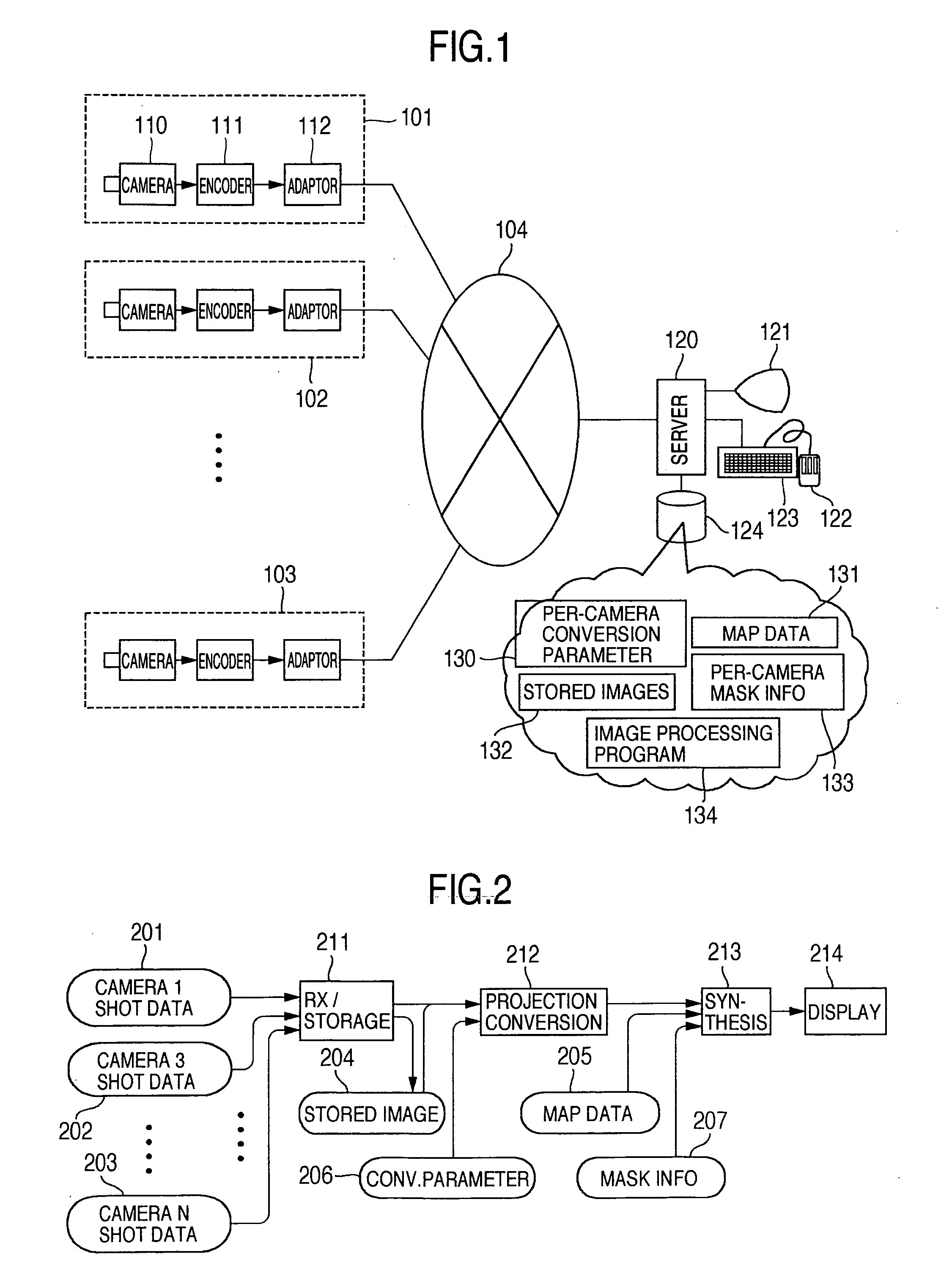
[0035] Referring to FIG. 1, there is shown a configuration of a surveillance system which collects surveillance camera images via a network, synthesizes them into map data, and visually displays an image thus synthesized. A plurality of network video cameras 101, 102, 103 transmit their acquired images to a video image collecting and browsing server 120 over a network 104. The network camera 101 acquires a scene image by using a camera 110, performs compression encoding of the image data by an image encoder 111, and sends forth the captured or “photographed” image data to the network through a network adapter 112. The video collecting / browsing server 120 is equipped with an external storage device 124 for storing therein several information items such as accumulative surveillance camera image data 132, map data 131 of an area under surveillance, per-camera conversion parameters 130 necessary for the synthesis of a camera-captured image and map data, per-camera mask inf...

embodiment 2

[Embodiment 2]

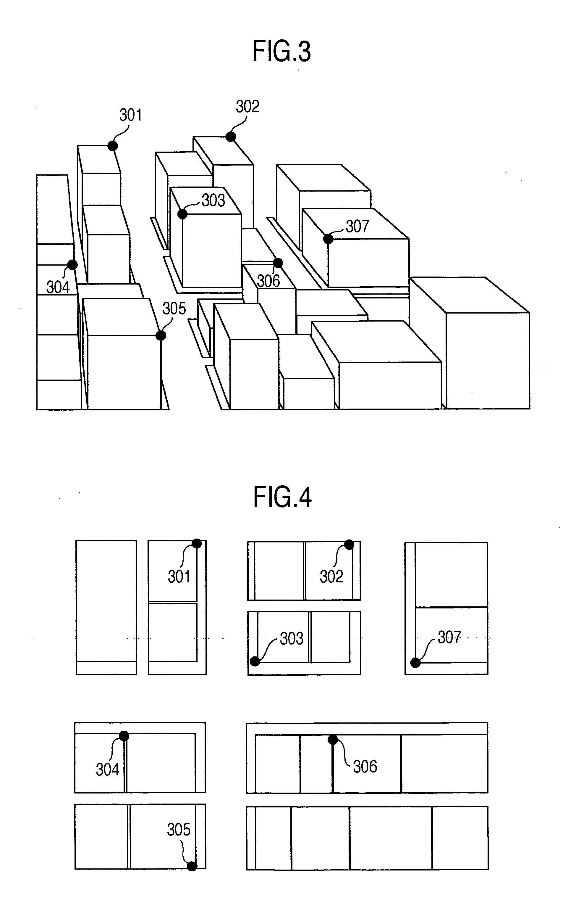
[0060] In the surveillance system explained in Embodiment 1, in cases where a scene image acquired by the surveillance camera 303 that is installed in the city block shown in FIG. 3 and an image captured by the monitor camera 304 are different in imaging time from each other, it is hardly expected to display the status at a given instant in the entirety of the surveillance area. For this reason, in the image with road status images of two separate cameras being synthesized together as shown in FIG. 11, the image portion of a moving object, such as for example a land vehicle, is photographed so that the same automobile was present at different road surface positions in the overlapped part of the mask information 901 and mask information 1001. This causes in some cases a problem in quality of the image synthesized, such as undesired synthesis and display thereof in a double offset manner like a ghost.

[0061] Consequently in the second embodiment, its feature lies in that...


PUM


Abstract

A surveillance system includes an image deformation unit for deforming the image captured or picked up by a surveillance camera so that the appearance of a specified region within this image has the same geometric shape as that of its corresponding region on the map, and an image synthesis display unit operable to extract the specific region of the deformed image and synthesize it in the corresponding map region for on-screen visualization, obtaining the mutual relationship of a plurality of images.

Description

INCORPORATION BY REFERENCE [0001] The present application claims priority from Japanese application JP2004-097560 filed on Mar. 30, 2004, the content of which is hereby incorporated by reference into this application. BACKGROUND OF THE INVENTION [0002] This invention relates to an apparatus, system and method for combining together images taken by camera devices placed at a plurality of locations to generate for display a synthesized or composite image. More particularly, the invention relates to a surveillance camera system and a surveillance camera image display method. [0003] A surveillance work by means of a surveillance system using monitor cameras generally includes performing image acquisition by use of at least one or more surveillance cameras capable of capturing a portion or the entirety of an area under surveillance, and also includes displaying the captured scene images on a video image display device such as a cathode ray tube (CRT) that is installed at a remote locatio...

Claims


Application Information

Patent Timeline
Patent Type & Authority Applications(United States)
IPC IPC(8): G06V10/24H04N5/225G06T3/00H04N5/232H04N5/262H04N7/18
CPCG06K9/00785G06K2009/2045G06K9/32G06V20/54G06V10/16G06V10/24
Inventor YAMASAKI, MASAMI
Owner HITACHI LTD
Why Eureka
Try Eureka