
Bollard and cable vehicle barrier

a cable vehicle and boltard technology, applied in roadway safety arrangements, roads, construction, etc., can solve the problems of slow activation of hydraulic actuators, difficulty and time-consuming after-sales repair, prior art devices are difficult and time-consuming to repair, etc., and achieve the effect of expanding the path width

Inactive Publication Date: 2005-10-06
BLAIR JOEY W +1
View PDF15 Cites 27 Cited by
  • Summary
  • Abstract
  • Description
  • Claims
  • Application Information

AI Technical Summary

Benefits of technology

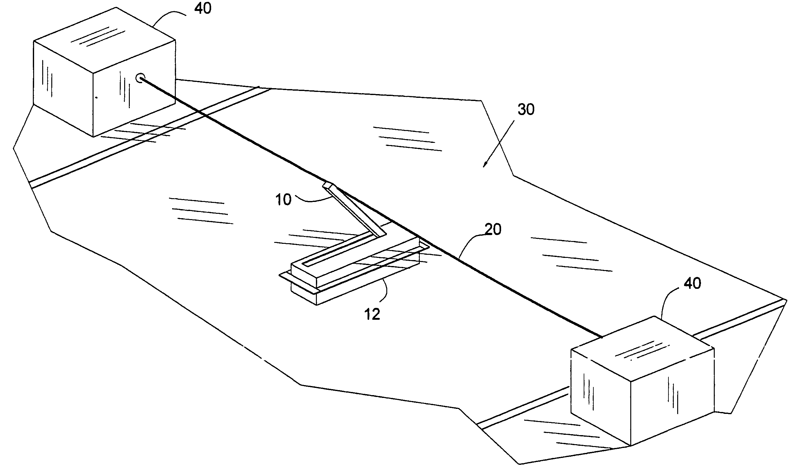
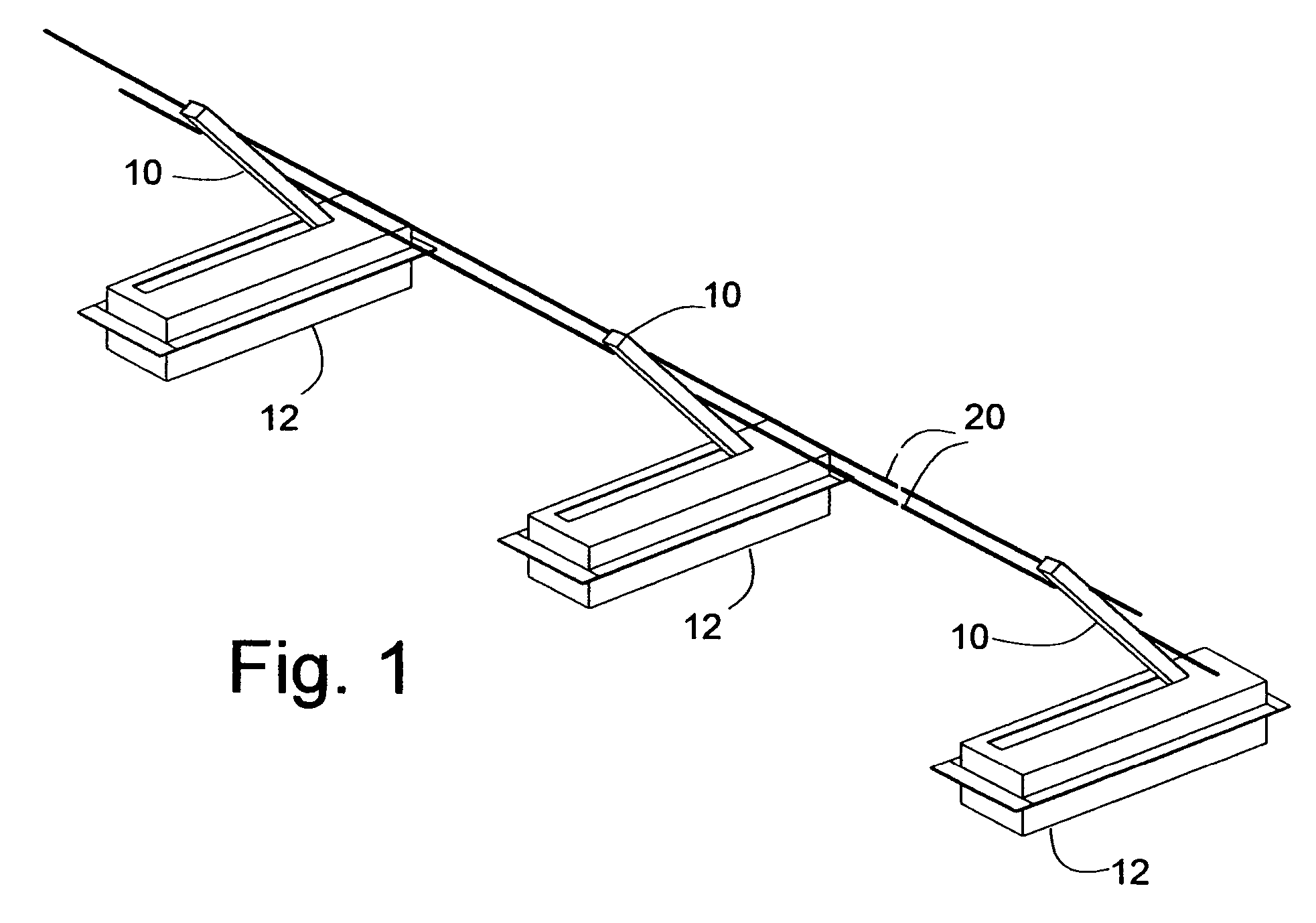
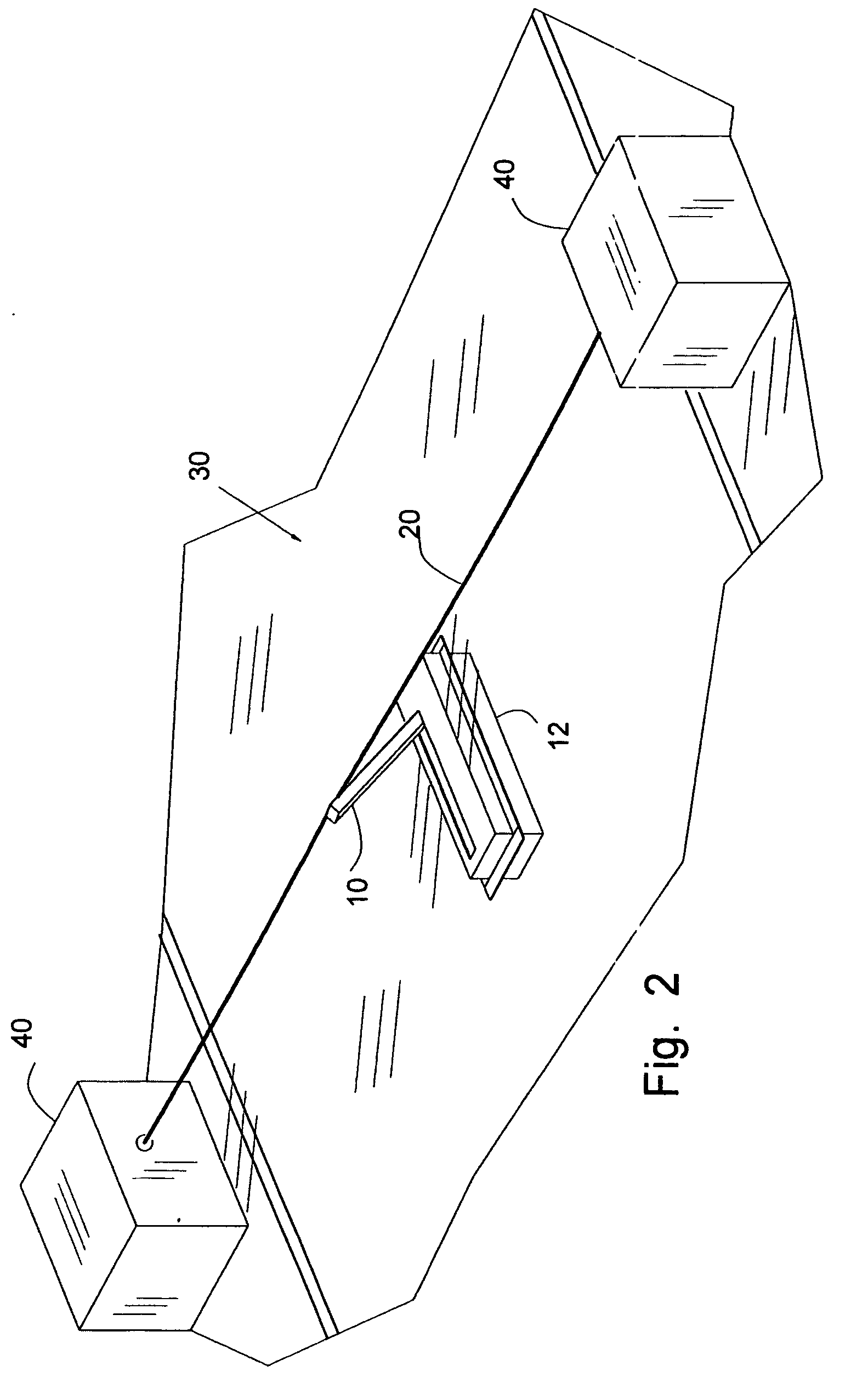
[0014] The present invention is a barrier formed by one or more cables, or other similar flexible elongated barrier elements, that have a ground level condition when in storage and have a raised condition when active as a barrier. The ground level condition allows movement of vehicles over the barrier element due to the small size of the barrier element. The raised condition is enabled by one or more flush below-surface mounted bollards to which the barrier element is secured and retained. The bollards are each rotated from a flush down condition to an upright orientation to elevate the barrier element.
[0016] One object of the invention is a simple and inexpensive collapsible vehicle barrier capable of protecting an extensive path width.

Problems solved by technology

A large disadvantage of this prior art device is that once a vehicle crashes into the device it is difficult and time consuming to repair afterwards.
Here again, this prior art device is difficult and time consuming to repair after a crash.
Moreover, the hydraulic actuator is slow in activation.
Moreover, this prior art device has a similar problem of being difficult and time consuming to repair following a crash.
This device has a similar problem of being difficult and time consuming to repair following a crash.
Additionally, prior art techniques do not suggest the present inventive combination of component elements as disclosed and claimed herein.

Method used


Image

  • Bollard and cable vehicle barrier
  • Bollard and cable vehicle barrier
  • Bollard and cable vehicle barrier

Examples


Embodiment Construction

[0024] Referring now to the drawings and to FIG. 1 in particular, multiple bollards 10 are shown retaining and elevating barrier elements that have the form of two flexible steel cables 20. The condition shown is a raised condition, wherein cables 20 are elevated by the bollards 10 above respective bollard vaults 12. The vaults 12, in use, are buried into, and flush with, the surface of a vehicle path. In most cases, the vehicle path is formed of pavement directly on the ground.

[0025] In a stored or down condition, the bollards 10 are each received within, and flush to, the top of its respective bollard vault 12. In this condition, the cables 20 are flush to the vehicle path.

[0026] In operation, as a vehicle barrier, the bollards 10 are raised to place the cables 20 in the path of a vehicle. The cables 20 intercept the vehicle and prevent continued motion of the vehicle past the cables 20. The vehicle's energy is absorbed by the cables 20, bollards 10 and vaults 12. The vehicle fo...


PUM


Abstract

A below-grade collapsible bollard and cable vehicle barrier system disposed in a vehicle pathway. The system comprises one or more bollard devices that include a vault located in the vehicle pathway, a rod rotatably mounted inside the vault, a bollard having a first end coupled to the rod, whereby rotation of the rod rotates the bollard to extend the second end thereof above the vehicle pathway. An actuator is secured within the vault for rotating the rod and thus raising the bollard. A cable is disposed perpendicular to the vehicle pathway with each end thereof affixed to anchors on either side of the pathway. The middle of the cable is affixed to the second end of the bollard. When the bollard is raised the cable is stretched across the pathway forming a barrier to traffic.

Description

CROSS REFERENCE TO RELATED APPLICATIONS [0001] This patent application is a continuation of Provisional Application No. 60 / 557,506, filed Mar. 30, 2004, and incorporates elements of the inventor's currently pending U.S. patent application Ser. No. 11 / 001,105, filed Dec. 1, 2004, and its parent U.S. patent application Ser. No. 10 / 641,452, filed Aug. 16, 2003, all of which are by the same inventors hereof.FIELD OF THE INVENTION [0002] The present invention generally relates to the field of collapsible below-grade barriers which may be employed as a barrier to vehicle movement. In particular, the present invention provides a simple below-grade mounted bollard and cable system providing a collapsible barrier protecting a wide spatial area. BACKGROUND OF THE INVENTION [0003] 1. Field of the Invention [0004] The present invention relates generally to an automatic collapsible self-contained, below-grade traffic barrier bollard and cable system which may be installed with a minimum amount o...

Claims


Application Information

Patent Timeline
Patent Type & Authority Applications(United States)
IPC IPC(8): E01F13/08E01F13/12E01F15/00
CPCE01F13/08E01F13/123
Inventor BLAIR, JOEY W.TURPIN, ROBERT R.
Owner BLAIR JOEY W
Learn More