Roll on/roll off ramp-deck transport platform
a technology for transporting platforms and ramps, applied in the field of transport platforms, can solve the problems of reducing limiting the utility of the platform and the number of platforms, and the thickness of the platform and the deck is relatively larg
- Summary
- Abstract
- Description
- Claims
- Application Information
AI Technical Summary
Benefits of technology
Problems solved by technology
Method used
Image
Examples
first embodiment
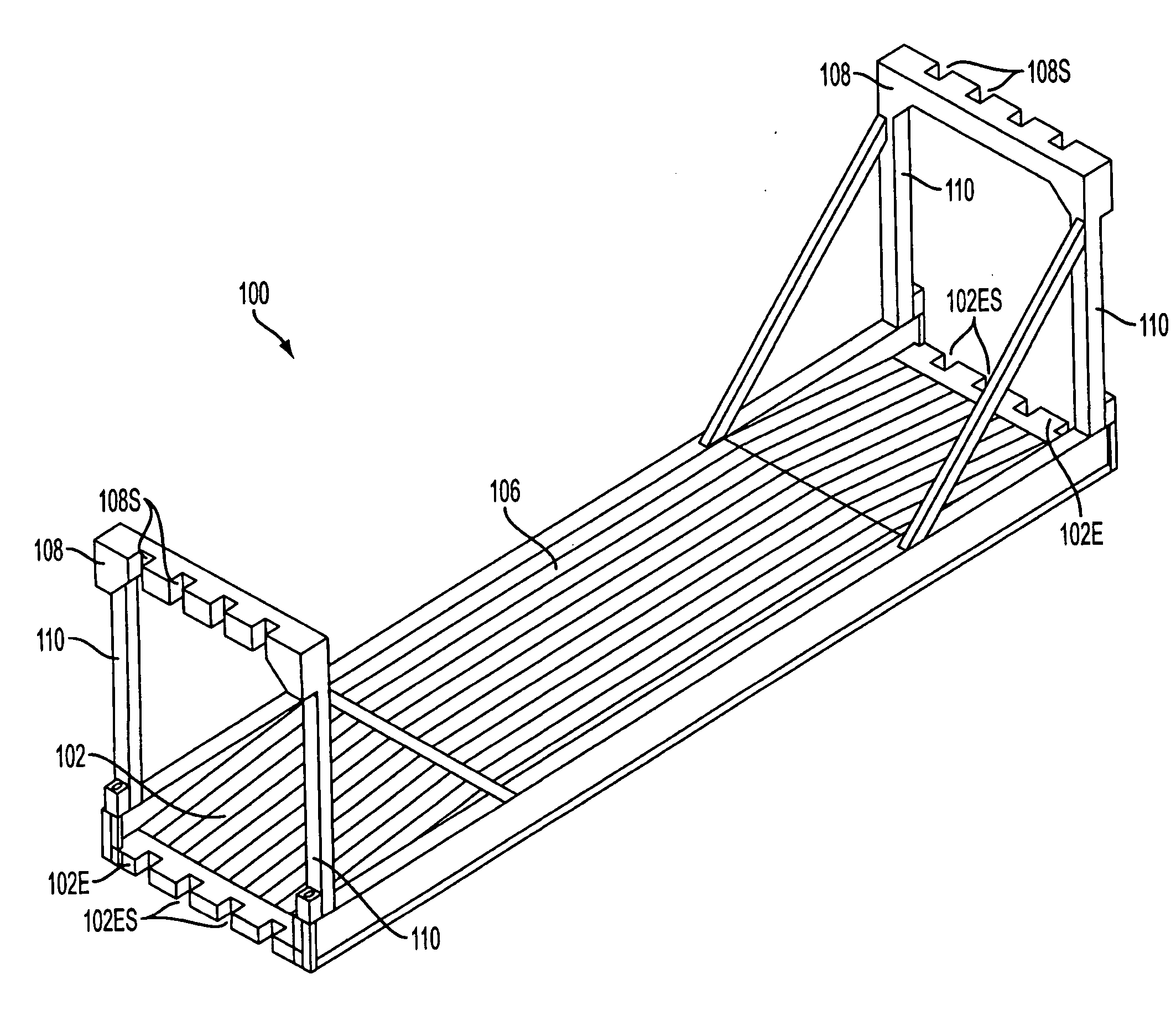
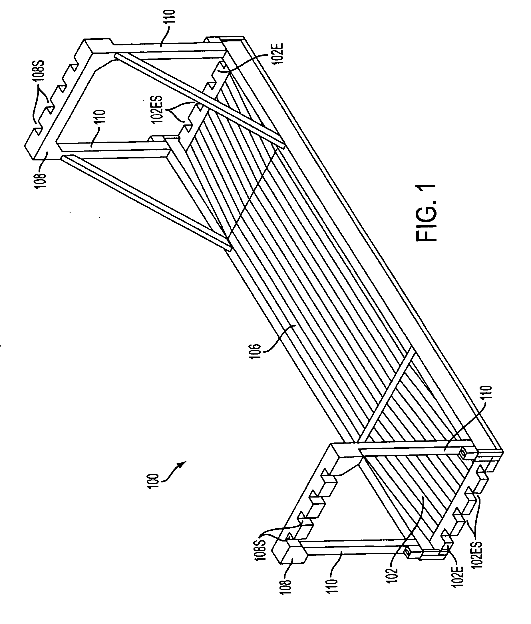
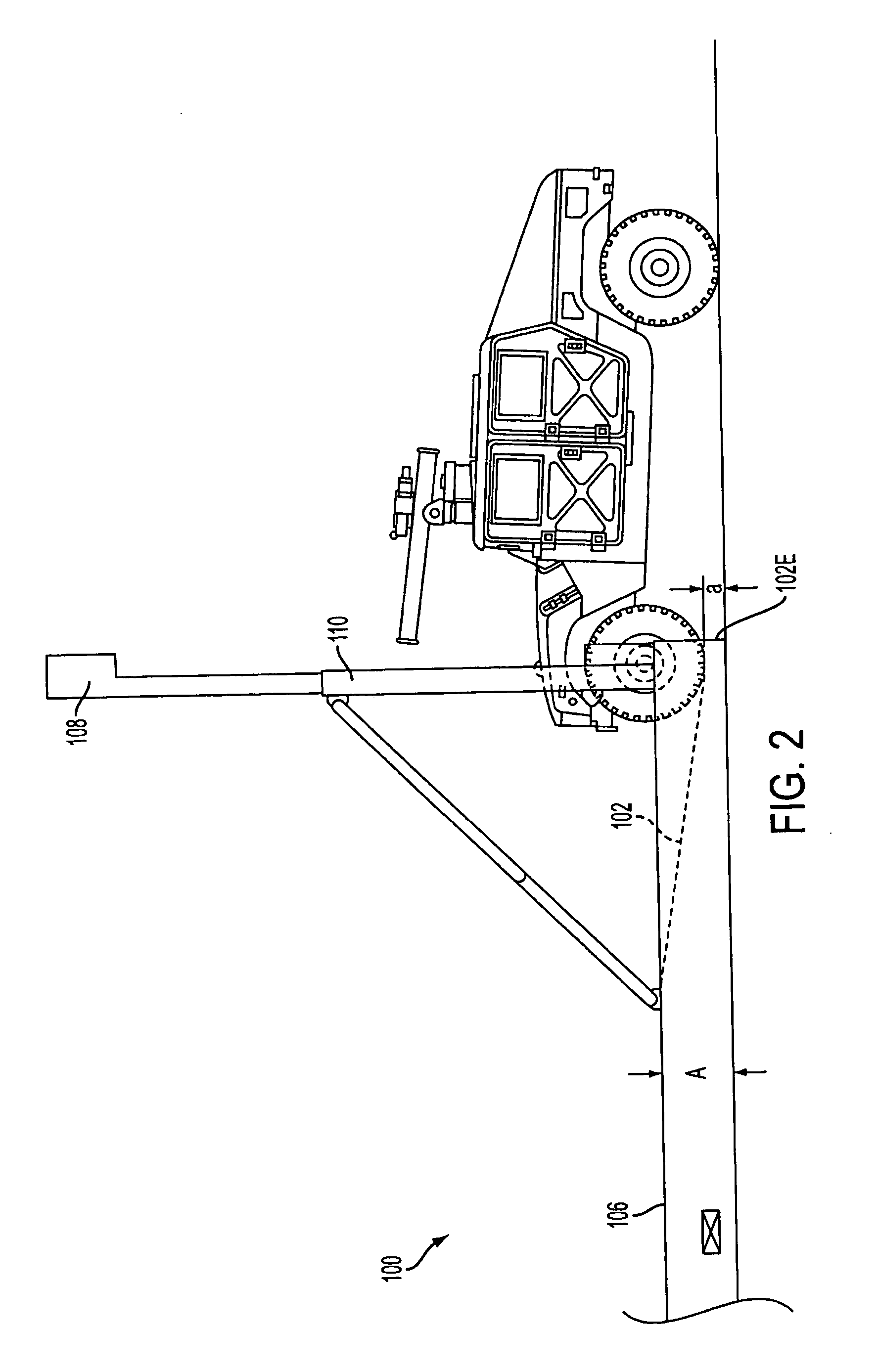
[0037]FIG. 1 is a perspective view of an easy roll on / roll off ramp-deck transport platform 100 according to the invention. This platform 100 is constructed so that both of the two opposed end portions 102 of the platform 100 are sloped and lead from an essentially flat, horizontal central portion 106 to each end of the platform. This sloping deck construction reduces the vertical height of the edges 102E of the platform from “A” to “a” in the manner depicted in FIG. 2.
[0038] This reduction in vertical height (A→a), wherein “A”, by way of example only, can be about 24″ and “a” can be about 6″, renders the edges 102E of the platform 100 readily traversable by wheeled vehicles in the manner illustrated in FIG. 2 Hence, with no moving parts or the need for additional structures such as ramps and the like, medium sized wheeled / track vehicles such as SUV (Sports Utility Vehicles) and even smaller vehicles (wheeled or tracked vehicles) are able to drive up and onto the platform with relat...
second embodiment
[0042]FIG. 5, in this instance is such as to show a stack of 40′ ISO containers C4 (note that two 20′ containers can be placed end to end in place of a 40′ container); four stacks of transport platforms TPS (TPS-1 . . . TPS-4) according to the invention; and a further stack of ISO containers C5, which are disposed in a hold HLD in the illustrated manner. The bulkhead B / H is shown as having a plurality of vertically extending T-guide members T / G rigidly connected thereto. Cell guides Cg1, Cg2, Cg3 . . . Cgn in which ISO containers can be slidably disposed, are defined between each adjacent two of the T-guide members T / G. Empty cell guides Cg8, Cg9 are shown at a right hand side of the figure.
[0043] The slots 102ES and 108S are aligned with one another and spaced in a predetermined relationship with the distance between the T-guides T / G. The width of the slots is selected to allow for ship-to-ship variations in the dimensions of the T-guide members T / G and are such as to leave a small...
third embodiment
[0056] Support blocks 360 are provided on either the deck or the masts to engage the mast when it is in a folded position and extends essentially parallel to the top of the deck. Further, the deck and mast are provided with projections 362, 363 which in this embodiment are essentially triangular in shape. These projections 362, 362 are use to connect the ends of an angled braces (not shown in this figure) which establish a reinforcing triangulation. In this third embodiment, these angle braces maintain the masts upright during use.
[0057] These projections 363 can also be used as connection sites for tie-down cables / chains if so required.
[0058] The hinges 365 in this third embodiment are constructed so that the pivot shaft is a bolt which can be removed to allow the mast be disconnected / replaced or the like.
[0059] As shown in FIG. 19, further outwardly extending projections 367 are provided on the masts. These projections 367 are slotted and are arranged so that the slots align wit...
PUM
 Abstract
Description
Claims
Application Information
 - R&D
- Intellectual Property
- Life Sciences
- Materials
- Tech Scout
- Unparalleled Data Quality
- Higher Quality Content
- 60% Fewer Hallucinations
Browse by: Latest US Patents, China's latest patents, Technical Efficacy Thesaurus, Application Domain, Technology Topic, Popular Technical Reports.
© 2025 PatSnap. All rights reserved.Legal|Privacy policy|Modern Slavery Act Transparency Statement|Sitemap|About US| Contact US: help@patsnap.com


