

Manipulator apparatus
- Summary
- Abstract
- Description
- Claims
- Application Information
AI Technical Summary
Benefits of technology
Problems solved by technology
Method used
Image

Examples
first embodiment
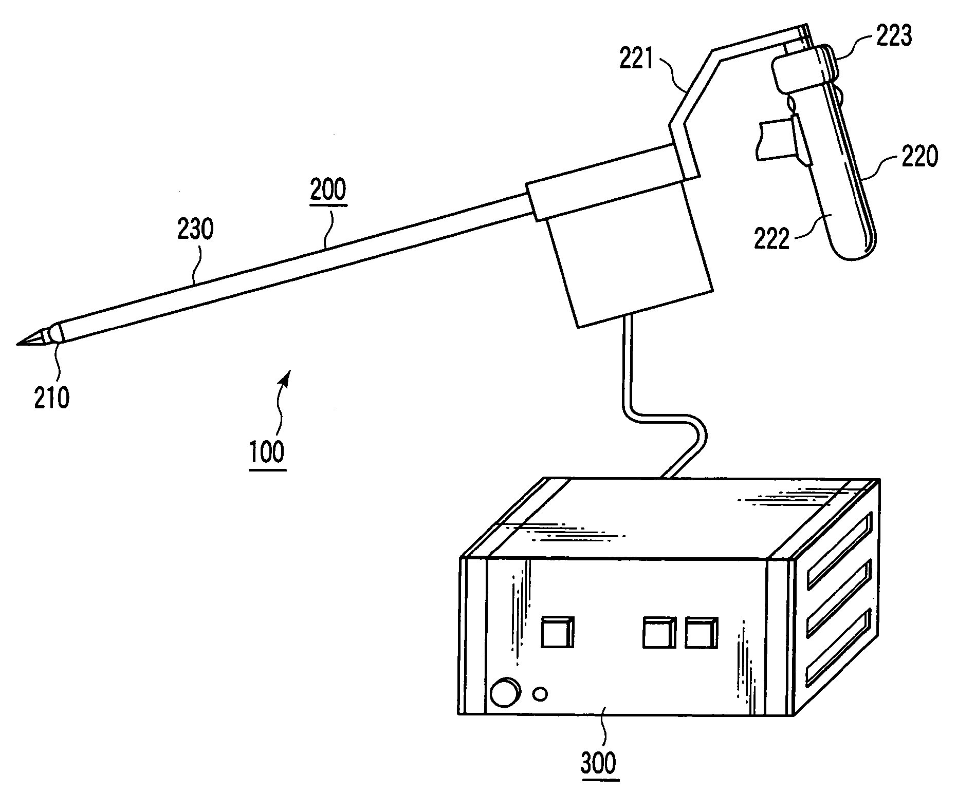
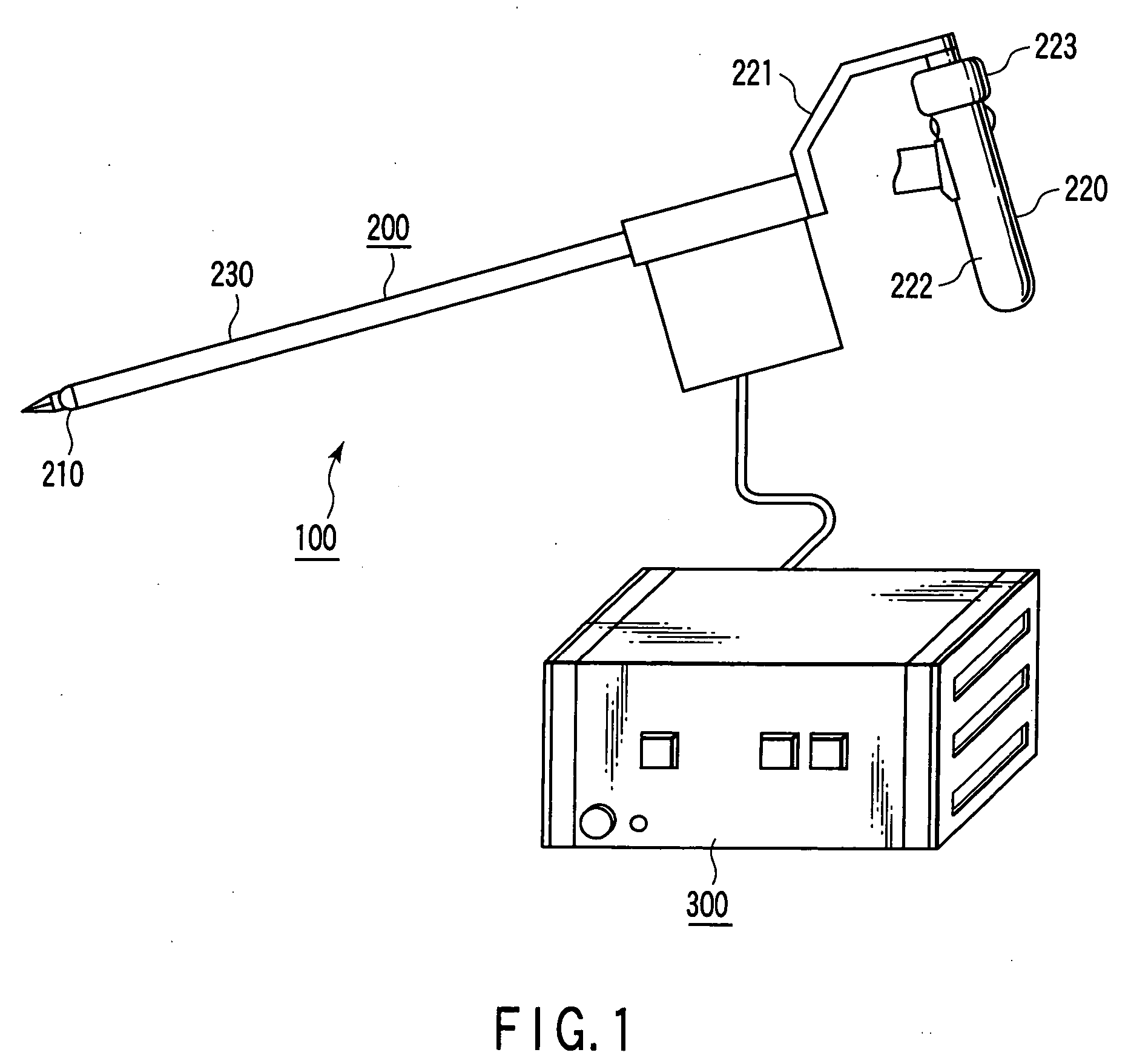
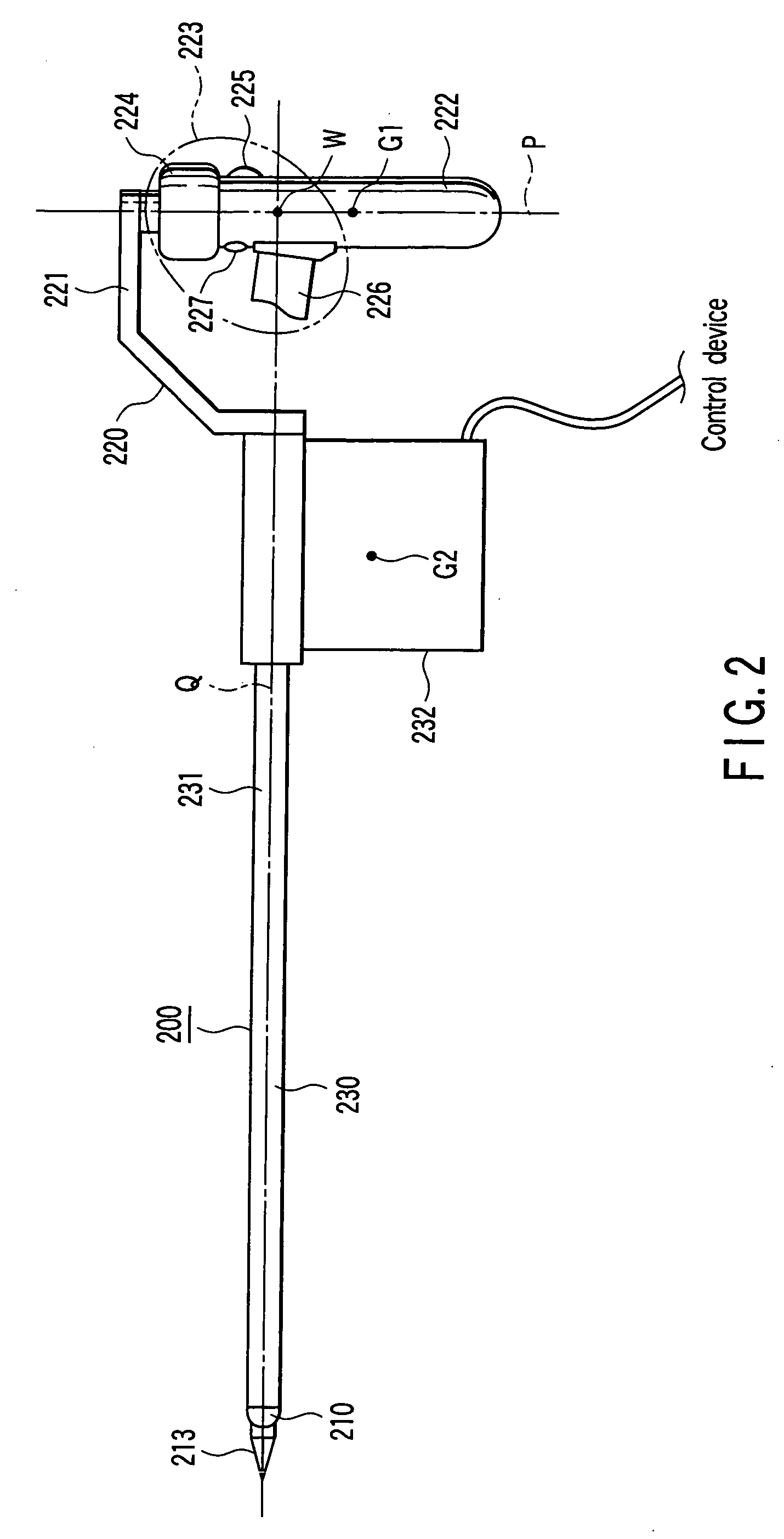
[0050]FIG. 1 is a perspective view showing a medical manipulator system 100 according to the present invention; FIG. 2 is a side view showing a medical manipulator 200 incorporated in the medical manipulator system 100; FIG. 3 is a perspective view showing a supporting section 210 incorporated in the medical manipulator 200; FIG. 4 is an illustrative view illustrating a manipulating section 220 incorporated in the medical manipulator 200; FIG. 5 is an exploded perspective view showing essential portions of the manipulating section 220; and FIG. 6 is a block diagram depicting a configuration of a control device 300 incorporated in the medical manipulator 100.
[0051] As shown in FIG. 1, the medical manipulator system 100 comprises: the medical manipulator 200 which operates in a master slave system; and the control device 300 which controls and drives the medical manipulator 200.
[0052] As shown in FIG. 2, the medical manipulator 200 comprises: the supporting section 210 inserted into ...
second embodiment
[0116]FIGS. 22 and 23 are views showing essential portions of a medical manipulator 270 according to the present invention. In FIGS. 22 and 23, like functional elements in FIGS. 2, 4 and 12 are designated by like reference numerals, and a detailed description is omitted here.
[0117] The medical manipulator 270 comprises: a roll axis joint 271 mounted at the distal end side of the arm member 231; the pitch axis joint 211 turnably supported by the roll axis joint 271 in the roll axis direction; the yaw axis joint 212 turnably supported by the pitch axis joint 211 in the pitch axis (first axis) direction; and the surgical treatment device 213 turnably jointed by the yaw axis joint 212 in the yaw axis (second axis) direction. The surgical treatment device 213 is openably configured. The surgical treatment device such as a radio knife does not require any opening or closing operation.
[0118] The manipulating section 220 comprises: the bracket 221 connected to the proximal end side of the ...
third embodiment
[0125]FIG. 25 is a side view showing essential portions of a medical manipulator 280 according to the present invention. In FIG. 25, like functional elements in FIG. 2 are designated by like reference numerals. A detailed description is omitted here.
[0126] The medical manipulator 280 comprises: the supporting section 210 to be inserted into the patient's body cavity; a manipulating section 281 to be manipulated by an operator; and the link section 230 for integrally linking the sections with each other.
[0127] The manipulating section 281 comprises: an arc shaped bracket 282 slidably connected to the proximal end side of the link section 230 in its peripheral direction (in the direction indicated by the arrow R in FIG. 25); the columnar manipulating lever 222 turnably mounted around the manipulating lever axis P with respect to the bracket 282; and the manipulating device 223 mounted on the manipulating lever 222.
[0128] The manipulating lever axis P which is the center axis of the ...
PUM
 Abstract
Description
Claims
Application Information