Exhaust gas cleaning device

a cleaning device and exhaust gas technology, applied in the direction of exhaust treatment electric control, electrical control, separation process, etc., can solve the problems of excessive temperature rise of catalyst or catalyst carrier, excessive catalyst temperature rise, storage nox may be released, etc., to reduce the amount of nox slip and the rate of catalyst temperature rise. , the effect of gradual ris

Inactive Publication Date: 2005-10-13
MITSUBISHI FUSO TRUCK AND BUS CORPORATION
View PDF16 Cites 44 Cited by
  • Summary
  • Abstract
  • Description
  • Claims
  • Application Information

AI Technical Summary

Benefits of technology

[0018] With the present invention, when the poisoning recovery timing judging unit judges that the timing for process execution has arrived, the added amount of the reducing agent, added from the reducing agent supplying unit, is made to increase gradually. The rate of temperature rise of the catalyst will thus be gradual. Also, if during the increase of the added amount of the reducing agent, the detected temperature from the temperature detection unit is lower than the thermal dissociation temperature of the NOx storage reduction catalyst, the air-fuel ratio changing unit is controlled to put the air-fuel ratio in a rich state. The NOx stored in the NOx storage reduction catalyst can thus be reduced before the NOx storage reduction catalyst reaches the thermal dissociation temperature, thereby lessening the amount of NOx slip that occurs when the thermal dissociation temperature is reached. Also, since the rate of temperature rise of the catalyst is made gradual, excessive rise of the temperature (excessive temperature rise) of the NOx storage reduction catalyst can be restrained.

Problems solved by technology

Since the SOx existing in the exhaust gas is stored by the NOx catalyst and moreover is not readily released from the catalyst even under conditions that are adequate for releasing the NOx stored in the catalyst (exhaust gas rich conditions), the SOx in the exhaust gas becomes gradually stored in the NOx catalyst to cause S poisoning as engine operation is continued.
However, since, even while the reducing components in the exhaust gas are eliminating the SOx, etc., that have become stored in the catalyst, the catalyst continues to be heated by the reaction heat of the reducing components, the catalyst temperature may undergo an excessive temperature rise and exceed a limiting temperature of the catalyst or the catalyst carrier.
Though a NOx storage catalyst can store NOx even at a temperature less than or equal to a reduction enabling temperature, if the catalyst temperature is raised in the process of performing S poisoning recovery control on the NOx storage catalyst, the stored NOx may become released due to thermal dissociation and NOx slip, in which the NOx becomes discharged without being cleaned, may occur in the transition to S poisoning recovery control.
Though a NOx storage catalyst can perform storage even at a temperature no more than a reduction enabling temperature, when the catalyst temperature is raised in the process of performing S poisoning recovery control on the NOx storage catalyst, the stored NOx becomes released due to thermal dissociation before the catalyst activation temperature is reached and NOx slip, in which the NOx becomes discharged without becoming cleaned, may occur in the transition to S poisoning recovery control.
Also, if the temperature is raised at once to the S poisoning recovery enabling temperature, the catalyst temperature may undergo an excessive temperature rise and exceed the limiting temperature of the catalyst or the catalyst carrier.

Method used


Image

  • Exhaust gas cleaning device
  • Exhaust gas cleaning device
  • Exhaust gas cleaning device

Examples


first embodiment

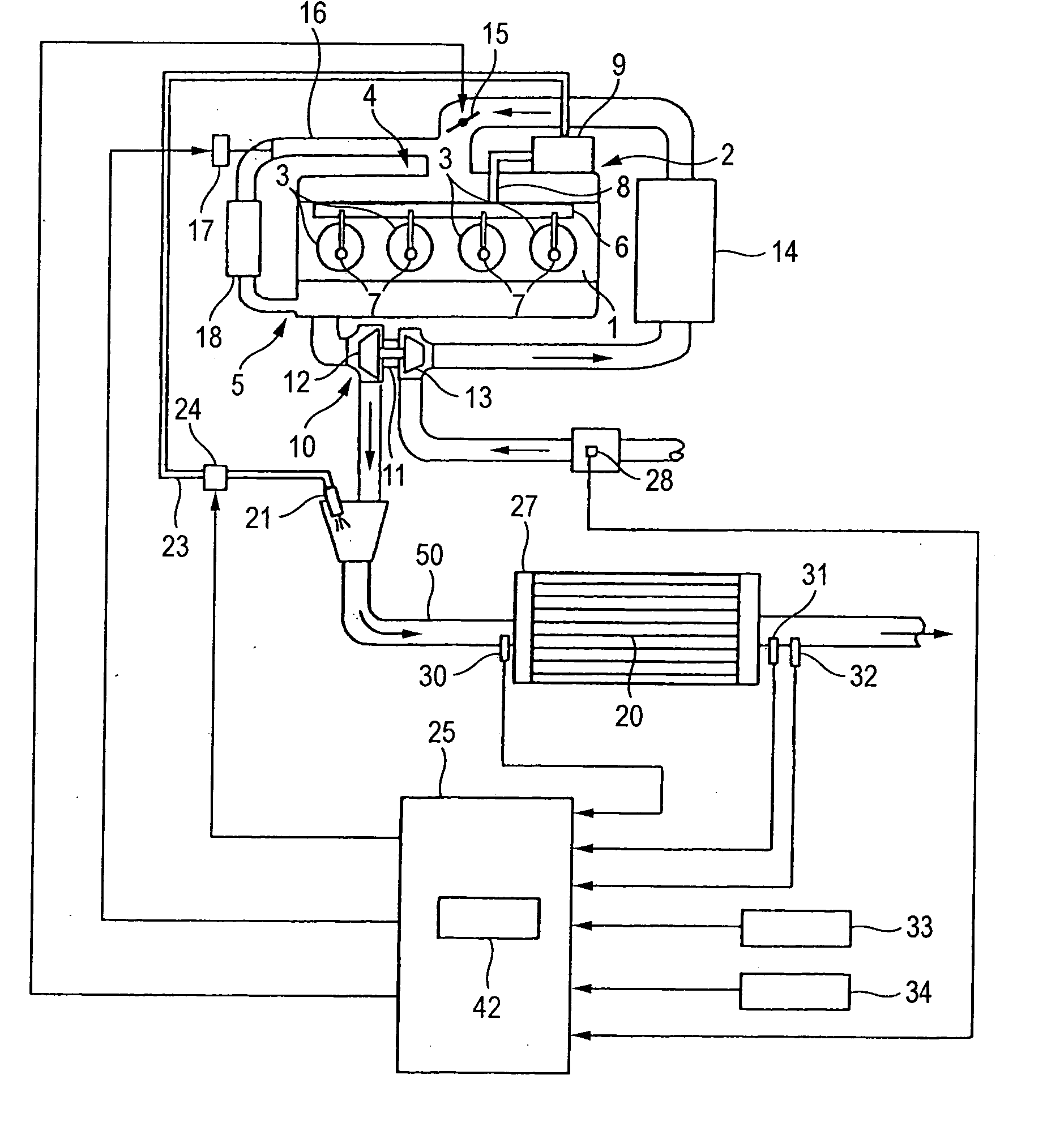
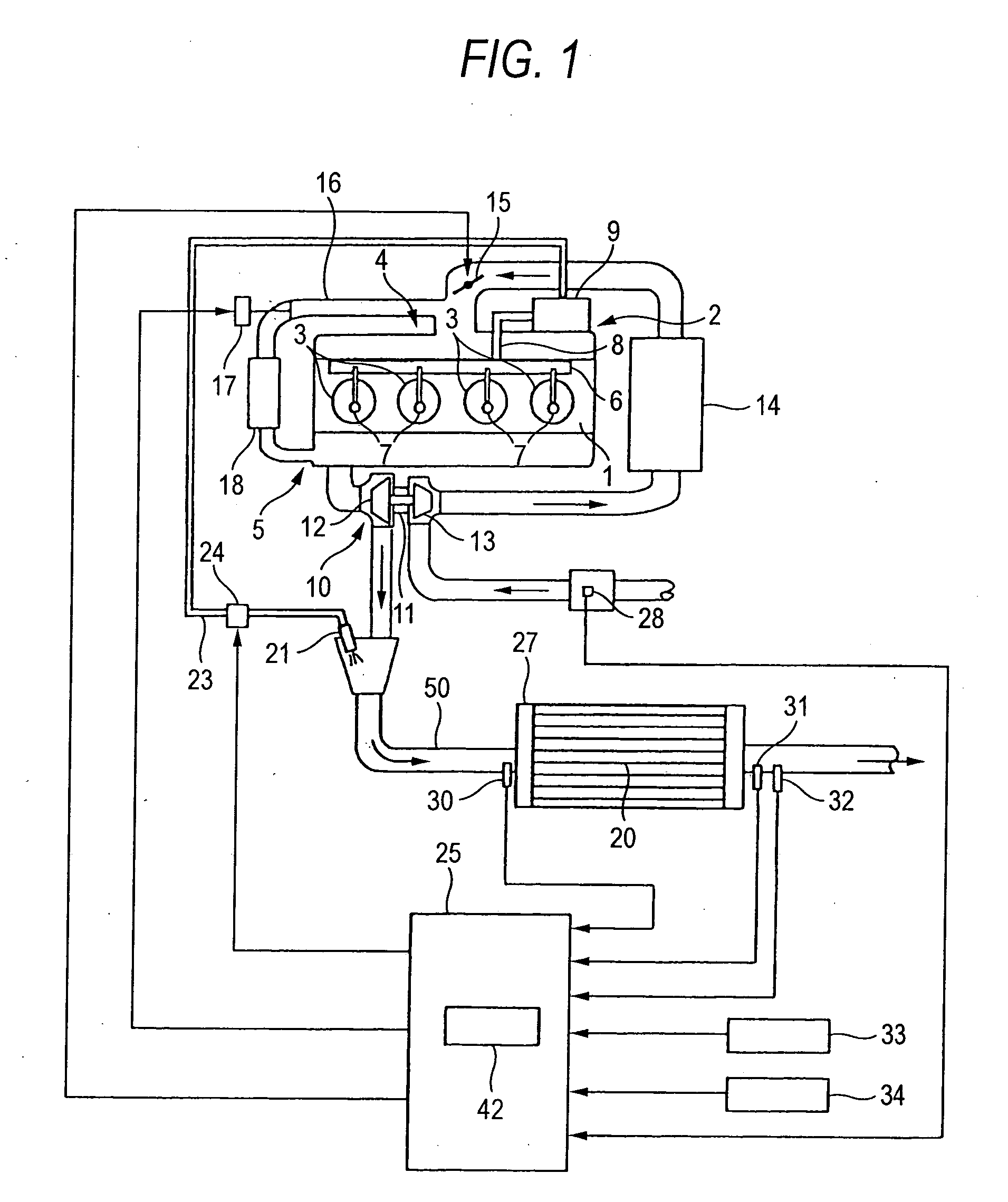
[0024]FIG. 1 shows an exhaust gas cleaning device, which is an embodiment of this invention. This exhaust gas cleaning device is applied to an internal combustion engine (referred to hereinafter as “engine”) 1. The engine 1 is a four-cylinder engine arranged with a fuel supply system 2, combustion chambers 3, an air intake system 4, an exhaust system 5, etc., as the principal parts. The fuel supply system 2 is equipped with a supply pump 9, a common rail 6, and injectors 7, which are the main injection unit and function as air-fuel ratio changing unit. The supply pump 9 is driven by the engine 1, applies high pressure to fuel pumped up from an unillustrated fuel tank, and supplies the fuel to the common rail 6 via an engine fuel passage 8. The common rail 6 functions as a pressure accumulating chamber that holds (accumulates the pressure of) the high-pressure fuel, supplied from the supply pump 9, at a predetermined pressure, and distributes the pressure-accumulated fuel among the i...

second embodiment

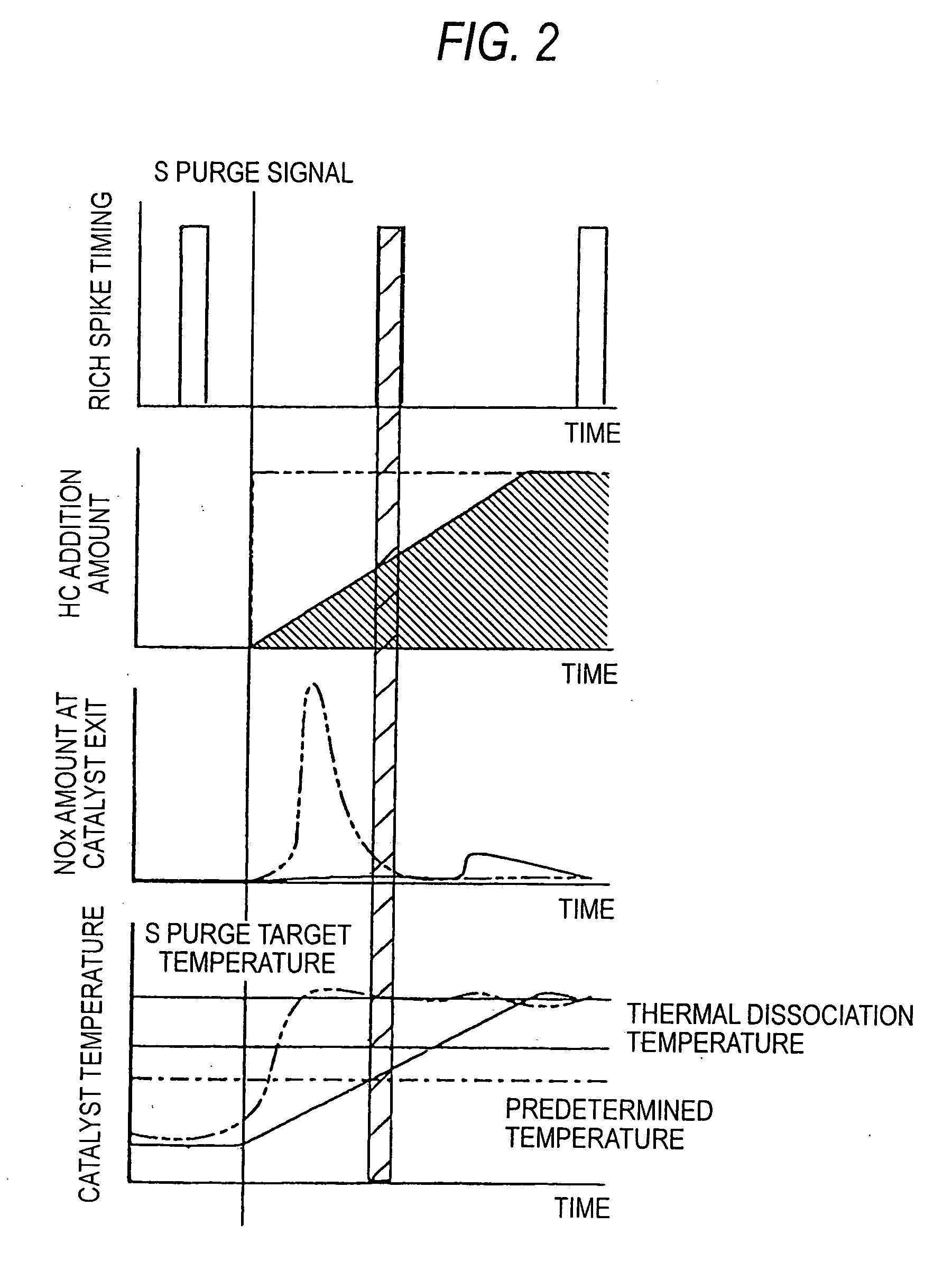
[0051] Newt, second embodiment of the invention will be described below. In this second embodiment, as shown in FIG. 4, in the S poisoning recovery control, a large amount of reducing components is supplied to the upstream side of the NOx catalyst in the exhaust system upon establishing the condition of maintaining the temperature of the NOx catalyst 20 at the S purge target temperature (600° C.) necessary for S poisoning recovery. However, though the large amount of reducing components supplied into the exhaust system exhibits the function of eliminating the SOx, etc., stored in the NOx catalyst 20 under the high-temperature condition, it also has the characteristic of raising the temperature of the NOx catalyst 20 further. Thus when the large amount of reducing components is supplied continuously to the upstream side of the NOx catalyst in the exhaust system, the NOx catalyst 20 may undergo excessive temperature rise, the stored NOx may become released due to thermal dissociation,...


PUM


Abstract

An exhaust cleaning device includes a NOx storage reduction catalyst storing NOx when an air-fuel ratio of an inflowing exhaust gas is lean and releasing the stored NOx when the air-fuel ratio of the inflowing exhaust gas is rich; an air-fuel ratio changing unit; a reducing agent supplying unit which adds a reducing agent to the NOx storage reduction catalyst; a temperature detection unit which detects a temperature of the NOx storage reduction catalyst; a poisoning recovery timing judging unit which judges a timing for executing a SOx poisoning recovery process of releasing SOx from the NOx storage reduction catalyst; and a control unit.

Description

BACKGROUND OF THE INVENTION [0001] 1. Field of the Invention [0002] This invention concerns an exhaust gas cleaning device for eliminating hazardous components and microparticles, etc., that are contained in the exhaust gas of an internal combustion engine. [0003] 2. Description of the Related Art [0004] With a lean-combustion-enabled internal combustion engine, such as a diesel engine, in which engine operation is performed by combustion of a mixed gas of high air-fuel ratio (lean atmosphere) within a wide operation range, a NOx catalyst, having the function of cleaning the exhaust gas of nitrogen oxides (NOx), is equipped in an exhaust passage of the engine. As the NOx catalyst, for example, a catalyst, wherein a NOx storage agent, having the ability to store NOx under the presence of oxygen, and a noble metal catalyst, having the ability to oxidize hydrocarbons (HC), are carried in combination by a carrier, formed of porous ceramic, etc., and having a honeycomb structure, is empl...

Claims


Application Information

Patent Timeline
Patent Type & Authority Applications(United States)
IPC IPC(8): B01D53/86F01N3/00F01N3/08F01N3/10F01N3/20F01N9/00F01N11/00F02B37/00F02D41/02
CPCF01N3/0814F01N3/0842F01N3/0885F01N2610/03F02B37/00F02D41/028F02D2200/0802F01N3/08F02D41/04F02D41/14
Inventor MURATA, MINEHIROTSUTSUI, YASUHIROKONDO, NOBUHIROTAKAHASHI, YOSHINORI
Owner MITSUBISHI FUSO TRUCK AND BUS CORPORATION
Why Eureka
Try Eureka