Muffler with catalytic converter arrangement; and method

a catalytic converter and muffler technology, applied in the direction of engines, mechanical equipment, machines/engines, etc., can solve the problems of not being able to reduce the size of the muffler, not having much if any room for effective placement being very limited in the space of the catalytic converter, etc., to achieve the effect of less durabl

Inactive Publication Date: 2005-10-13
DONALDSON CO INC
View PDF64 Cites 9 Cited by
  • Summary
  • Abstract
  • Description
  • Claims
  • Application Information

AI Technical Summary

Benefits of technology

[0017] In preferred arrangements wherein the catalytic converter core comprises ceramic, the ceramic core is provided in a generally cylindrical configuration, with an outer cylindrical surface. The ceramic core is preferably protected by the catalytic converter arrangement being provided with a flexible, insulating mantle wrapped around the core outer surface. The insulating mantle will preferably be secured in place by the positioning of an outer metal wrap therearound. In preferred arrangements the outer metal wrap is provided with side flanges, operably folded over upstream and downstream faces of the catalytic converter core. Preferably a soft, flexible insulating rope gasket is positioned adjacent any such folds or flanges, to inhibit crumbling of the ceramic core during the manufacture and installation process and to provide a seal for the less durable insulating mantle materials.

Problems solved by technology

For example, trucks typically have very limited space for the placement of catalytic equipment in the exhaust system.
The largest space available is occupied by the muffler, leaving little if any room for effective placement of a catalytic converter.
It is not generally reasonable to reduce the size of the muffler to allow for placement of a converter assembly.
In addition, in a diesel powered truck system the acceptable amount of resistance to flow in the exhaust stream is strictly limited.
The added backpressure which would be introduced by placement of a conventional catalytic converter arrangement in the exhaust stream (in addition to the conventional muffler) would typically be unacceptably close to (if not over) the maximum backpressure allowable and would reduce fuel efficiency.

Method used


Image

  • Muffler with catalytic converter arrangement; and method
  • Muffler with catalytic converter arrangement; and method
  • Muffler with catalytic converter arrangement; and method

Examples


Embodiment Construction

[0033] As required, a detailed description of preferred and alternate embodiments is presented herein. The description provided is not intended to be limiting, but rather to serve as a presentation by example of embodiments in which the subject matter claimed may be applied.

The General Configuration of the Overall Assembly

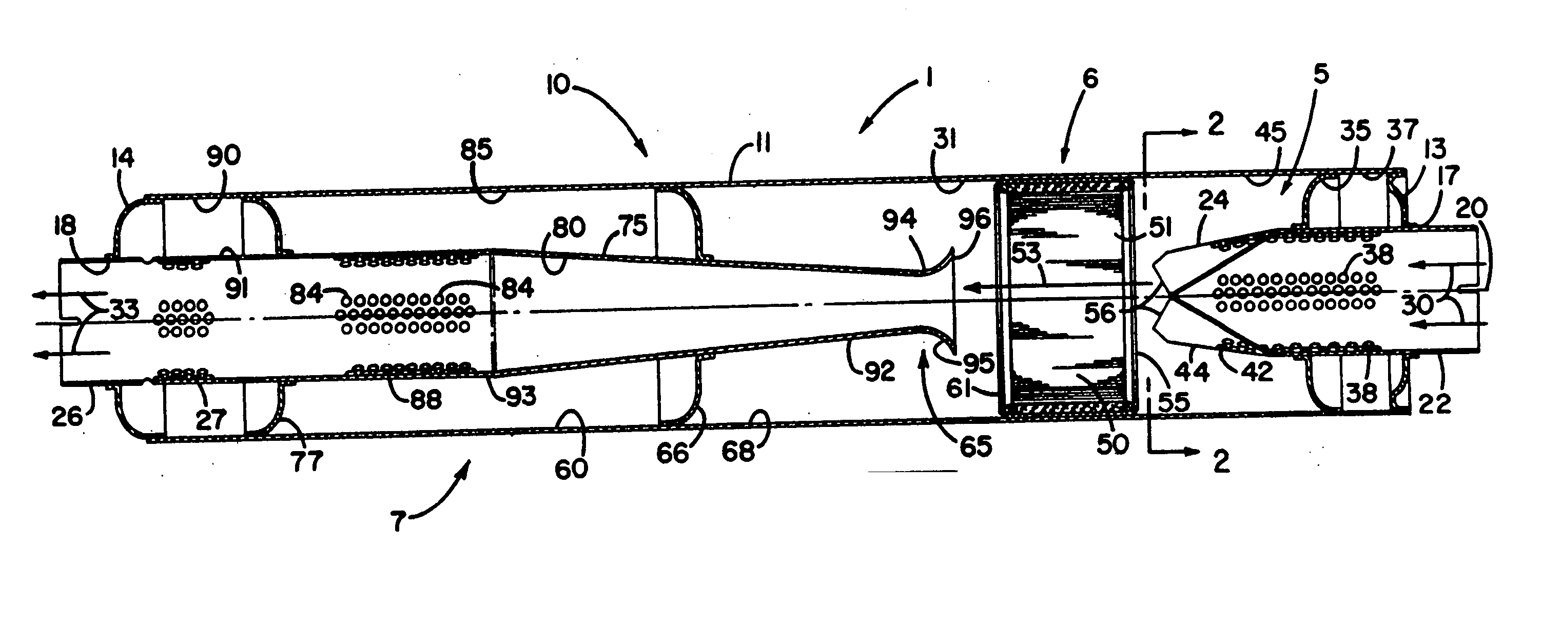
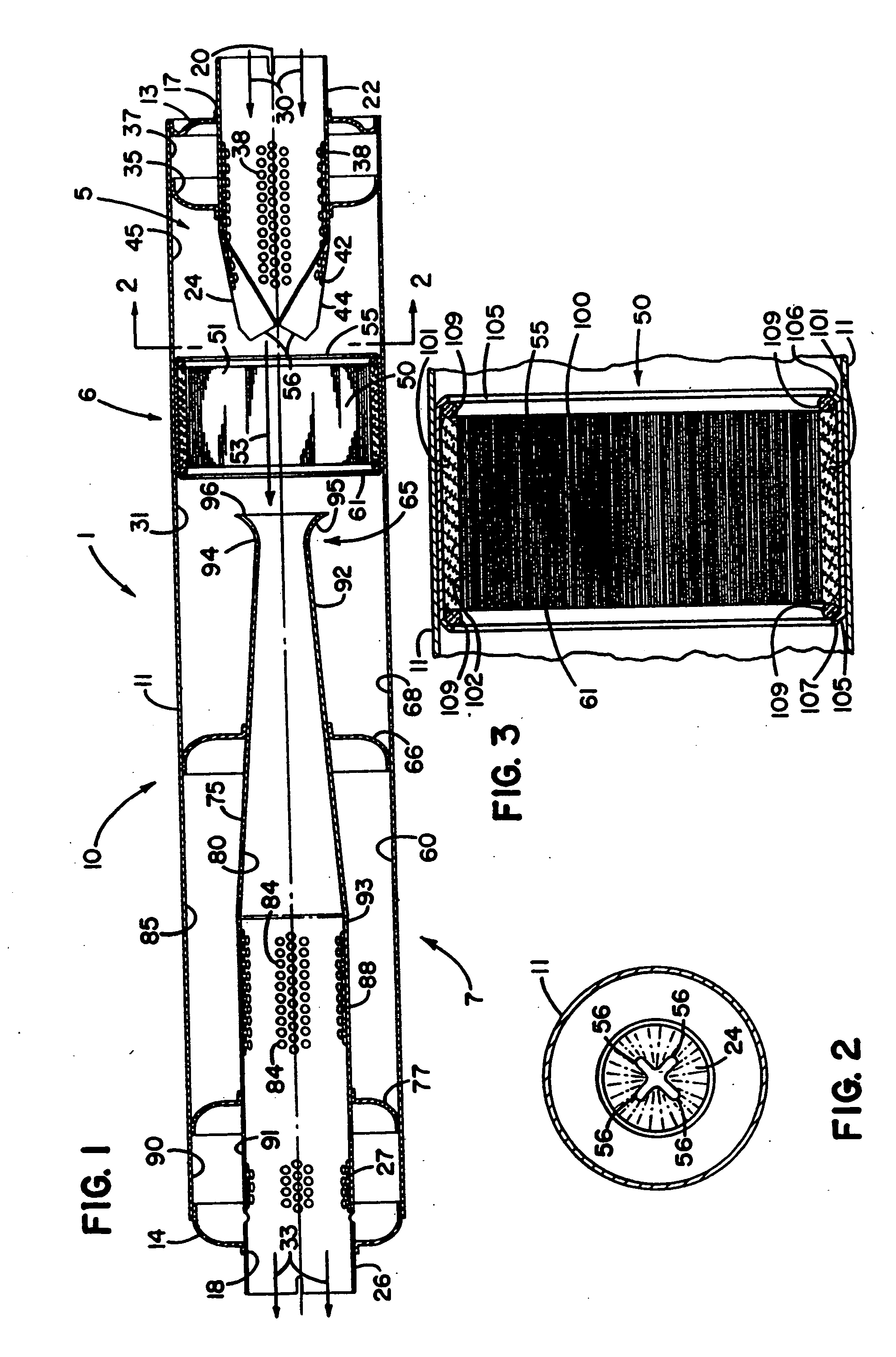
[0034] The reference numeral 1, FIG. 1, generally designates a muffler assembly according to the present invention. The muffler assembly 1 has defined therein three general regions: an exhaust introduction, distribution and upstream acoustics region 5; a catalytic converter region 6; and a downstream acoustical or attenuation region 7. Each of regions 5, 6 and 7 may be constructed separately, with the overall assembly prepared through utilization of appropriate clamps, segments, etc. However, in preferred applications as shown in FIG. 1, it is foreseen that the segments 5, 6 and 7 will be constructed in an overall unit 10 having an outer shell 11 with no segment...


PUM


Abstract

An apparatus for modifying an exhaust stream of a diesel engine is provided. The apparatus includes a muffler arrangement having an exhaust inlet and an exhaust outlet in construct and arrange for sound attenuation therein. The apparatus also includes a catalytic converter arrangement positioned within the muffler arrangement between the exhaust inlet and exhaust outlet. During operation, the exhaust flow is directed both through the muffler arrangement and the catalytic converter arrangement, to advantage.

Description

FIELD OF THE INVENTION [0001] The present invention relates to muffler assemblies and in particular to muffler assemblies of a type used to dampen exhaust noise produced by internal combustion engines. The invention specifically concerns such an arrangement having a catalytic converter therein. BACKGROUND OF THE INVENTION [0002] Catalytic converters have been widely utilized with internal combustion engines, typically gasoline powered engines. In operation an oxidizing catalytic converter comprises a post combuster through which emissions from the internal combustion process are directed. The catalyst promotes the conversion of carbon monoxides and hydrocarbons in the emissions to carbon dioxide and water vapor. [0003] In a typical application, the catalytic converter is located in the exhaust system as close to the exhaust engine manifold as practical. In this manner, advantage is taken of available heat in the exhaust gases to minimize the time lag in reaching the desired operatin...

Claims


Application Information

Patent Timeline
Patent Type & Authority Applications(United States)
IPC IPC(8): F01N1/00F01N1/02F01N1/08F01N3/10F01N3/28F01N7/00F02B3/06F02B27/02F02B27/06
CPCF01N1/003F01N1/02F01N1/08F01N3/2817F01N3/2857F01N3/2867F01N3/2885F01N3/2892F01N2230/04F01N2330/40F01N2470/02F01N2470/18F01N2470/20F01N2470/22F01N2470/30F01N2490/155F01N2490/20F02B3/06F02B27/06
Inventor WAGNER, WAYNE M.BARRIS, MARTY A.FLEMMING, DOUGLAS E.ROTHMAN, JAMES C.BETTS, PETER A.
Owner DONALDSON CO INC
Why Eureka
Try Eureka