

Retractable wire lock
a wire lock and lock body technology, applied in padlocks, building locks, constructions, etc., can solve the problems of easy theft, difficult movement and use of fixed length cables, and a lot of care for cables, so as to reduce the total size and facilitate carrying and storage
- Summary
- Abstract
- Description
- Claims
- Application Information
AI Technical Summary
Benefits of technology
Problems solved by technology
Method used
Image

Examples
first embodiment
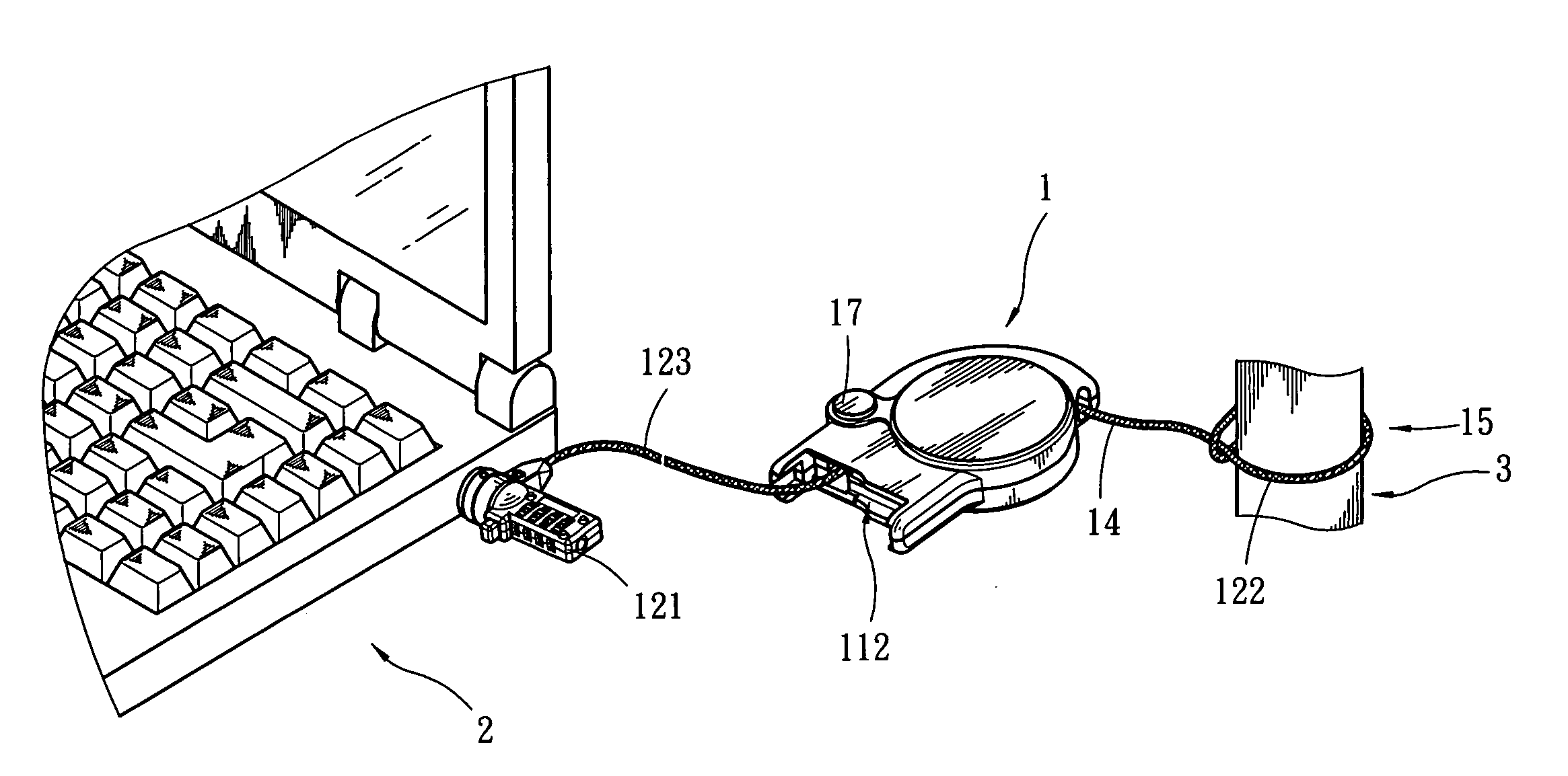
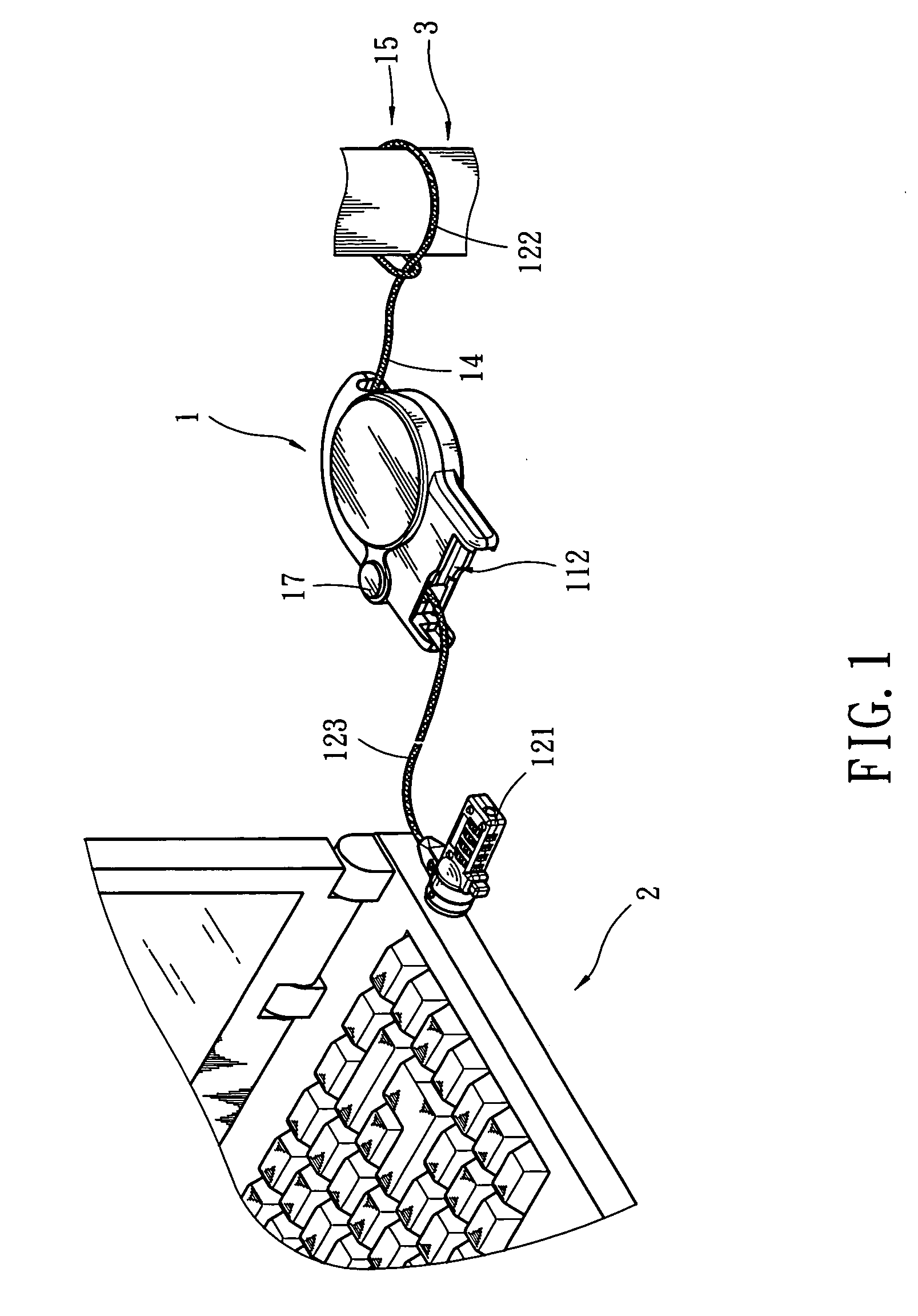
[0035] Refer to FIGS. 7A and 7B for the invention. The casing 11 has a housing compartment 112. The first guarding member 12 has an aperture 124 to couple with a pivot element 4 to enable the first guarding member 12, to be held in the housing compartment 112 at a storing position. When in use, the first guarding member 12 may be moved outwards from the casing 11 to fasten to the guarded object 2, or the first guarding member 12 may be turned about the pivot element 4 to be moved outside the housing compartment 112 to fasten to the guarded object 2. The second guarding member 15 may be pulled out by unwinding the second connection member 14 from the winding reel 13 to fasten to the anchor object 3 at a desired distance to provide a guarding effect.
second embodiment
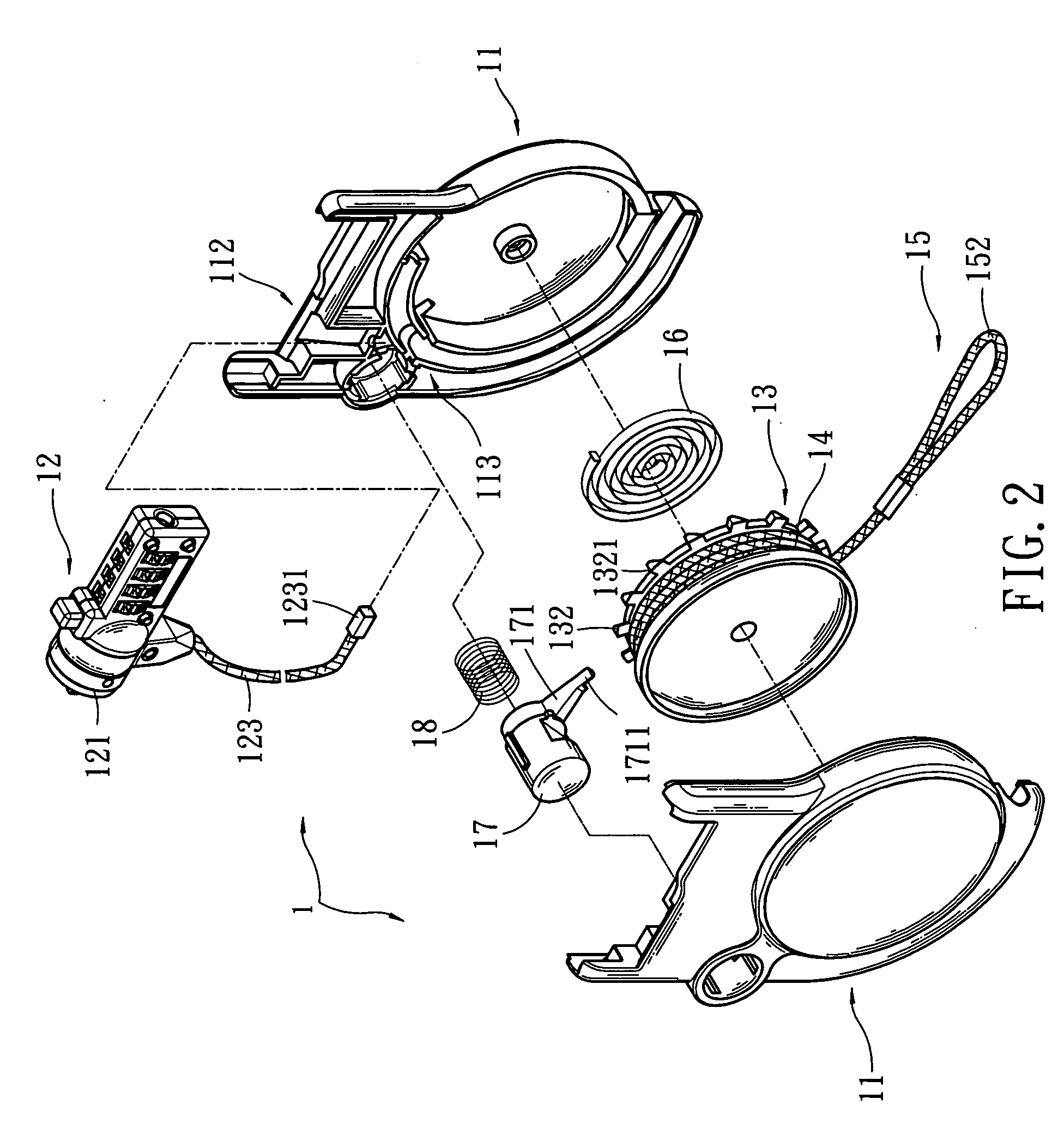
[0036] Refer to FIGS. 8A and 8B for the invention. It has a shared winding reel 13. This embodiment includes a casing 11, a first guarding member 12, a first connection member 14A, a winding reel 13, a second connection member 14B and a second guarding member 15. The winding reel 13 is pivotally coupled in the casing 11 and may be rotated therein.
[0037] The first guarding member 12 is fastened to the guarded object 2 and is coupled with the first connection member 14A which has the other end fastened to and wound on the winding reel 13.
[0038] The second guarding object 15 is fastened to the anchor object 3 and also is coupled to the second connection member 14B which has the other end fastened to and wound on the winding reel 13.
[0039] There is an elastic element 16 (referring to FIG. 2) located between the winding reel 13 and the casing 11. The elastic element 16 may be a spiral spring which has one end fastened to the casing 11 and the other end fastened to the winding reel 13. ...
third embodiment
[0041] Refer to FIGS. 9A and 9B for the invention. It adopts separated winding reels. This embodiment includes a casing 11, a first guarding member 12, a winding reel 13A, a first connection member 14A, a second guarding member 15, a second winding reel 13B, and a second connection member 14B. The first winding reel 13A and the second winding reel 13B are pivotally mounted on the casing 11, and are stacked in a coaxial manner or located on different axles, and are turnable therein.
[0042] The first guarding member 12 is fastened to one end of the first connection member 14A, which has the other end fastened to and wound on the first winding reel 13A.
[0043] The second guarding object 15 is fastened to one end of the second connection member 14B which has the other end fastened to and wound on the second winding reel 13B.
[0044] There is an elastic element 16 located respectively between the first winding reel 13A and the casing 11, and between the second winding reel 13B and the casi...
PUM
 Abstract
Description
Claims
Application Information