Apparatus for cleaning a rotating cylinder

a rotating cylinder and apparatus technology, applied in the field of apparatus for cleaning a rotating cylinder, can solve the problems of reducing the cleaning efficiency and affecting the cleaning effect of the cleaning apparatus,

a rotating cylinder and apparatus technology, applied in the field of apparatus for cleaning a rotating cylinder, can solve the problems of reducing the cleaning efficiency and affecting the cleaning effect of the cleaning apparatus,

US20050223926A1Inactive Publication Date: 2005-10-13PAPER CONVERTING MASCH CO INC

Image

  • Apparatus for cleaning a rotating cylinder
  • Apparatus for cleaning a rotating cylinder
  • Apparatus for cleaning a rotating cylinder

Examples


Embodiment Construction

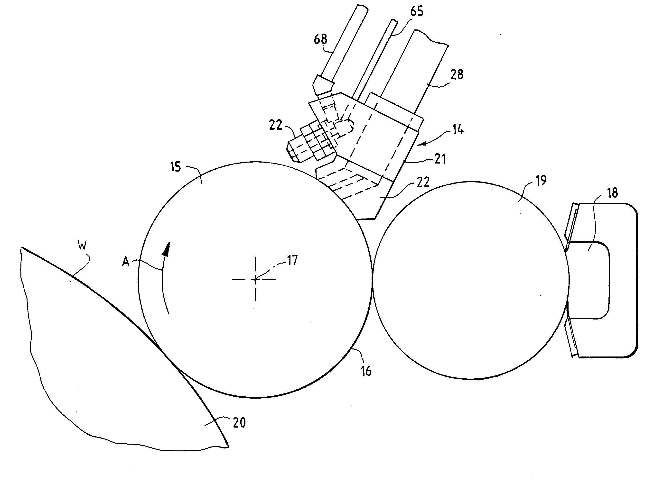
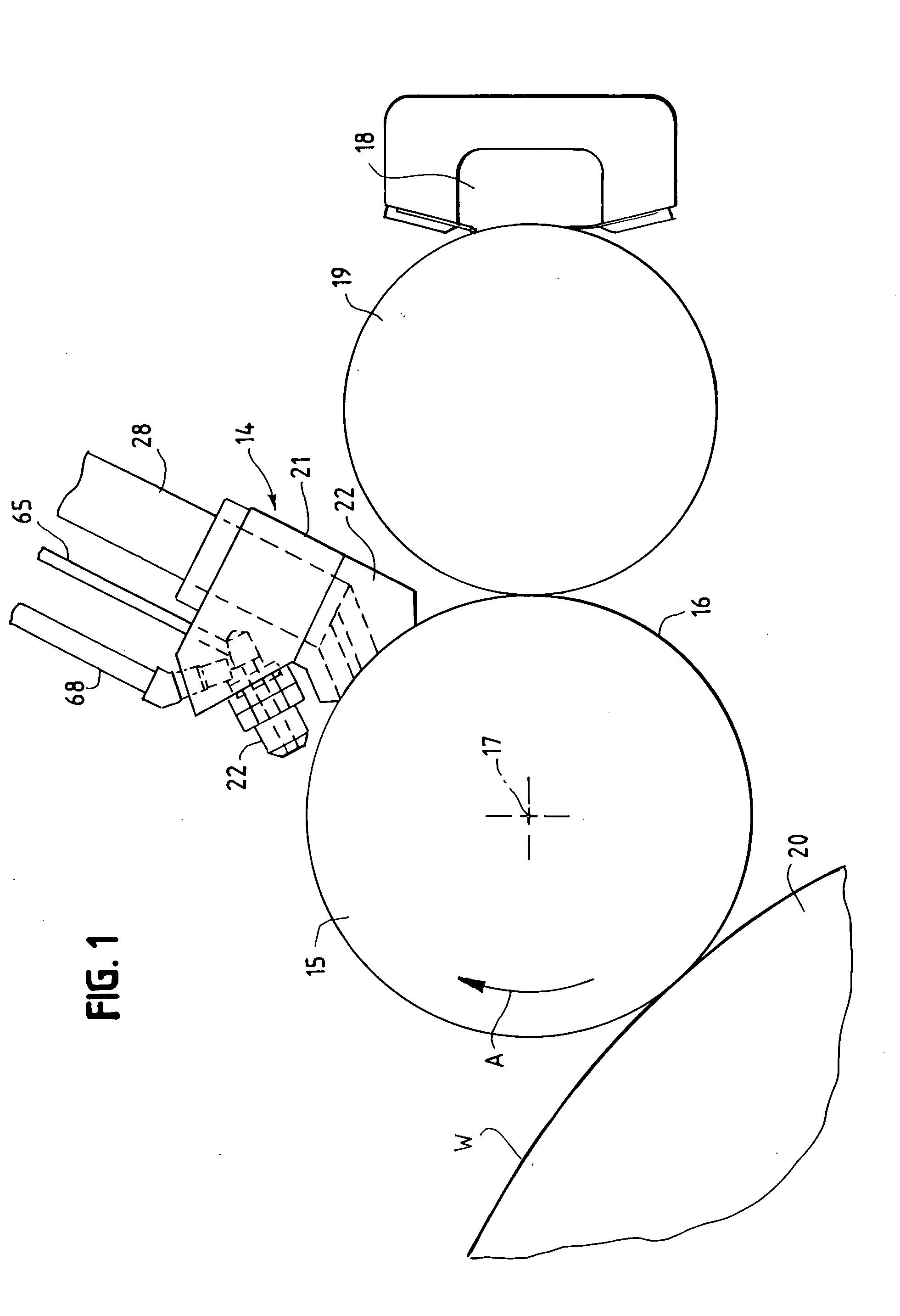
[0026] Referring to FIG. 1, a cleaning apparatus 14 is mounted adjacent a rotating cylinder 15. In the particular embodiment illustrated the cylinder is a plate cylinder of a flexographic printing press. The cylinder includes a cylindrical surface 16 which rotates about a longitudinal axis 17 in the direction of the arrow A.

[0027] Ink from a ink chamber 18 is supplied to the plate cylinder 15 by an anilox roll 19. A web W rotates with impression cylinder 20, and ink is transferred from the plate cylinder to the web.

[0028] The cleaning head is positioned to clean the plate after the ink is transferred to the web. Depending on the rotation of the plate roll, the cleaning head can be mounted above the axis between the anilox roll and plate roll, or below the axis between the plate roll and anilox roll.

[0029] As described in the prior art patents, the cleaning apparatus is mounted on a frame in a conventional manner which permits the cleaning apparatus to move axially along the plate...


PUM


Abstract

A plate cleaner for a printing press includes a cleaning head and a nozzle mounted on the cleaning head for directing pressurized fluid toward the plate cylinder of the printing press. The nozzle directs the pressurized fluid at an acute angle to a tangent to the cylinder in a direction opposite to the rotation of the plate cylinder. The cleaning head is provided with a suction port for removing contamination from the plate cylinder. The nozzle is located outside of the suction port.

Description

BACKGROUND [0001] This invention relates to an apparatus for cleaning a rotating cylinder. More particularly, the invention relates to a plate cleaner for cleaning the printing surface of a plate cylinder on a printing press. [0002] The invention is particularly useful for cleaning the plate cylinder of a flexographic printing press and will be explained in conjunction with such a press. However, it will be understood, that the invention is not limited to flexographic presses and can be used with other presses and with rotating cylinders other than printing plate cylinders. [0003] Flexographic printing presses are commonly used for printing webs for making paper towels and bathroom tissue and for printing other products. Such a press includes an impression cylinder and at least one plate roll or cylinder. During the printing process, ink is transferred to the printing surface of the plates from another roll (typically an anilox roll). The web travels over the impression cylinder. As...

Claims


Application Information

Patent Timeline
13 Oct 2005
Publication
US20050223926A1
IPC
B41L41/02; B41F35/06; B41F35/04; B41F7/30; B41F35/00; B41L41/00; B41L41/06; B41L41/04; B41F35/02
CPC
B41F35/02; B41P2235/26; B41P2235/27
Inventors
BAETEN, MICHAEL