
Plasma display panel

Inactive Publication Date: 2005-10-13
SAMSUNG SDI CO LTD
View PDF20 Cites 11 Cited by
  • Summary
  • Abstract
  • Description
  • Claims
  • Application Information

AI Technical Summary

Benefits of technology

[0010] It is therefore, one object of the present invention to provide a plasma display panel (PDP) having improved light emission efficiency.
[0013] According to one aspect of the present invention, there is provided a PDP having improved light emission efficiency is provided.
[0014] Also, in another aspect there is provided a PDP that facilitates the exhaustion of impure gases and the insertion of a discharge gas.
[0015] In yet another aspect, there is provided a PDP having improved light emission efficiency as a result of a reduction of the address voltage.

Problems solved by technology

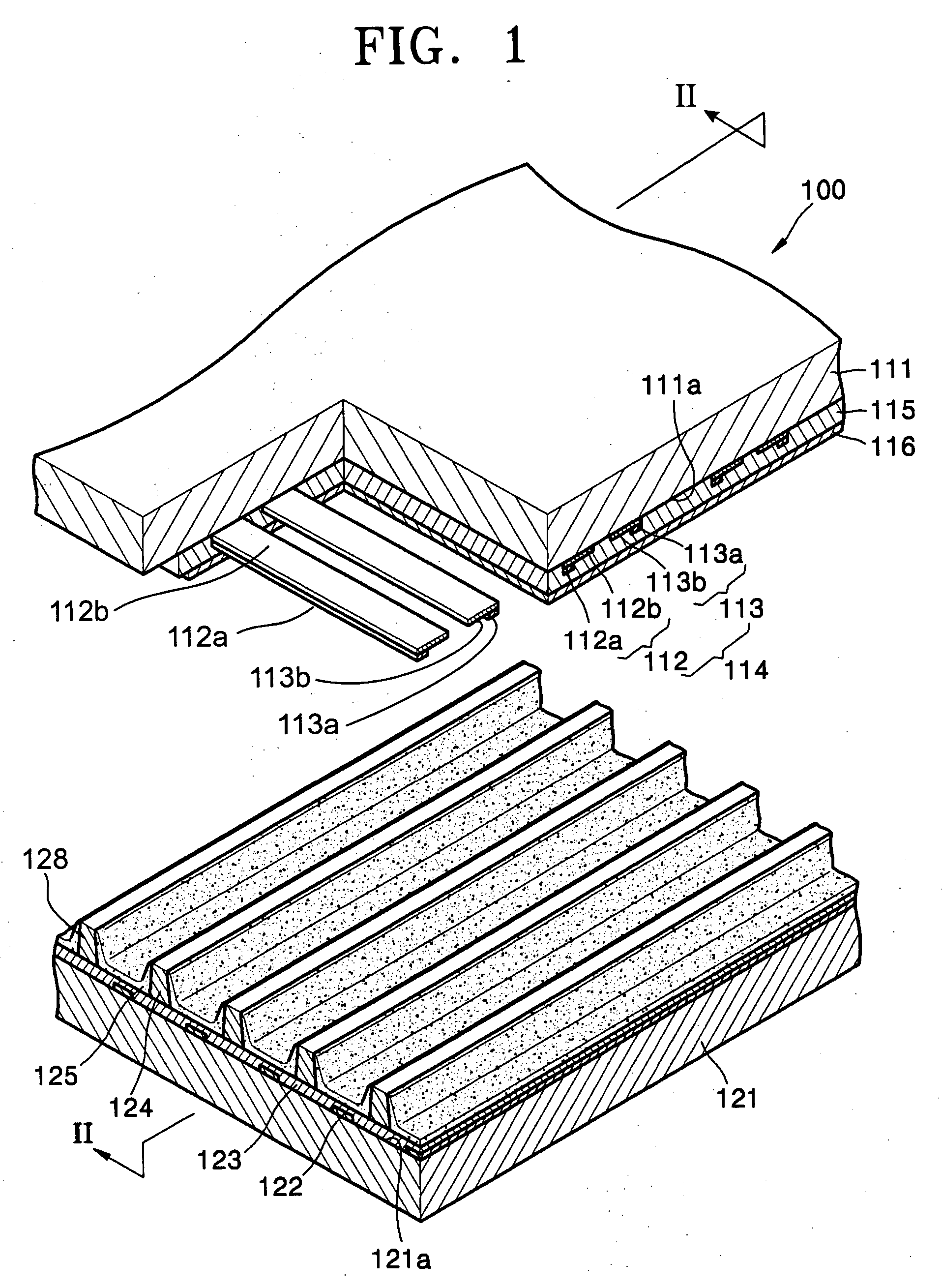
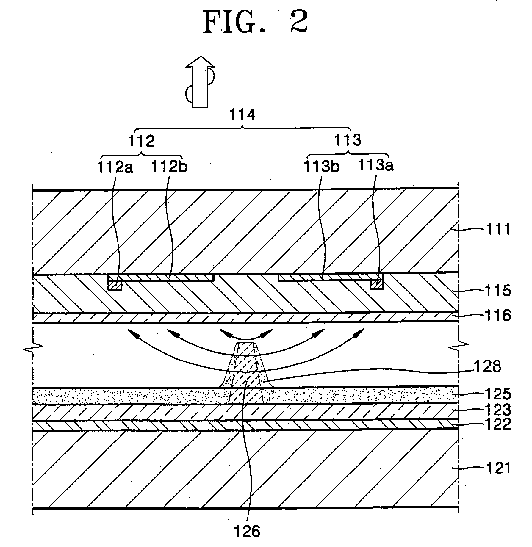
We have discovered that this structure is not desirable, however, because the central barrier rib may interrupt the sustaining discharge between the X electrode and the Y electrode.

Method used


Image

  • Plasma display panel
  • Plasma display panel
  • Plasma display panel

Examples


first embodiment

[0049] A first embodiment will now be described with reference to FIGS. 3 through 5.

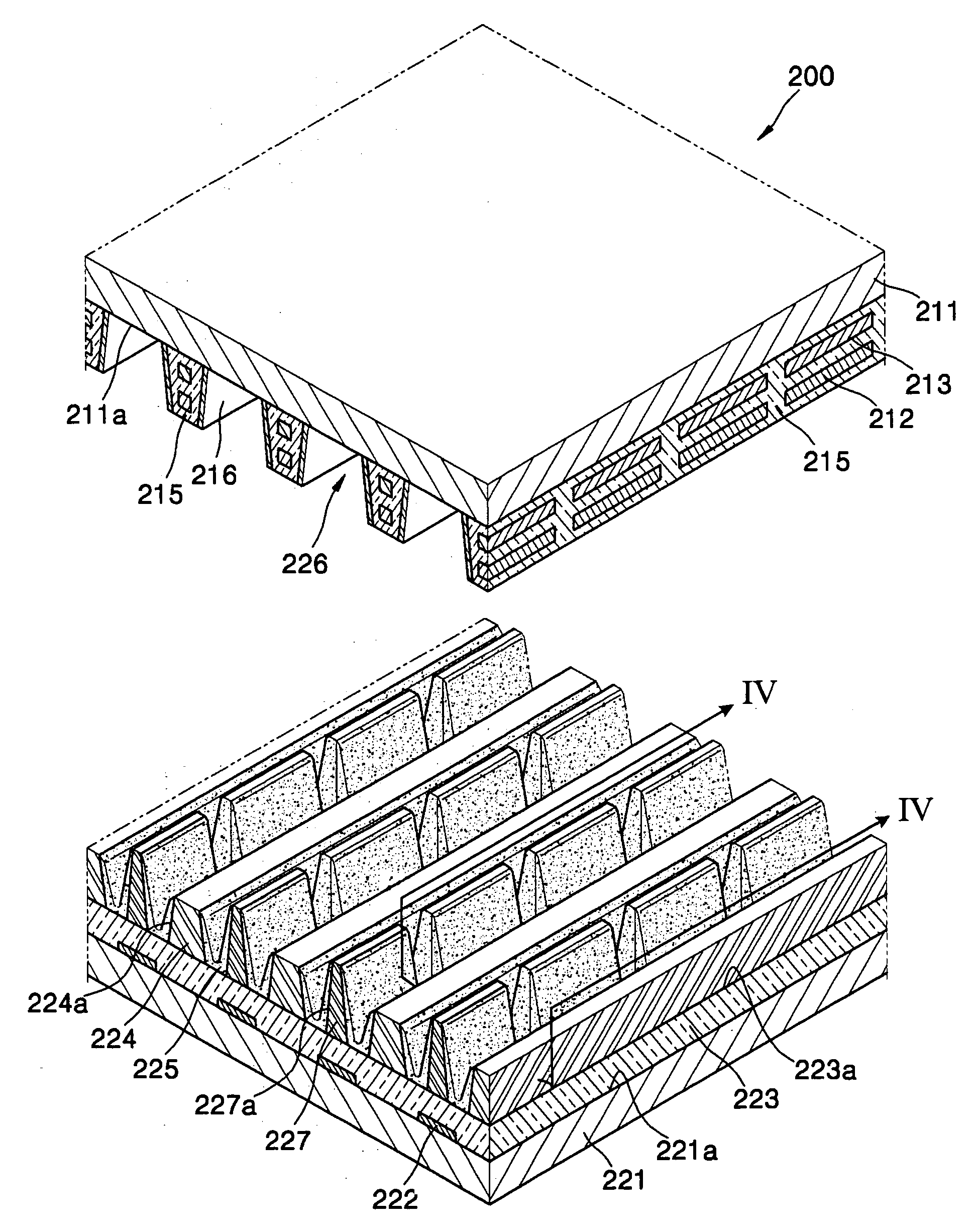
[0050]FIG. 3 is a cutaway exploded oblique view of a PDP according to one implementation of a first embodiment of the present invention, while FIG. 4 is a partial cross-sectional view taken along sectional line IV-IV of FIG. 3 and FIG. 5 is a partial oblique view illustrating the structure of electrodes in the PDP of FIG. 3.

[0051] A PDP 200 according to the first embodiment includes an upper substrate 211, an lower substrate 221 positioned within a plane parallel to a plane defined by upper substrate 211, a plurality of upper barrier ribs 215 descending downwardly from an undersurface of upper substrate 211, an upper discharge electrode 213 and a lower discharge electrode 212 embedded within each upper barrier rib 215, a plurality of lower barrier ribs 224 borne by and extending upwardly from lower substrate 221 toward corresponding ones of upper barrier ribs 215, a central barrier rib 227 centrally...

second embodiment

[0091] FIG.10 is a cutaway, partially exploded oblique view of a PDP constructed according to the present invention, while FIG. 11 is a partial cross-sectional view taken along sectional line XI-XI of FIG. 10.

[0092] One difference between the first and second embodiments is that in the construction of the second embodiments, lower barrier ribs 524 are formed in the same pattern as upper barrier ribs 215. Referring to FIG. 10, upper barrier ribs 215 define closed spaces in a horizontal direction, and lower barrier ribs 524 of the present embodiment also define closed spaces in a horizontal direction. In this embodiment, the area of side surface 524a of lower barrier ribs 524 is increased, and accordingly the area of fluorescent layer 225 is concomitantly increased. As a result, the amount of visible light emitted from a discharge cell 226 is also increased, thereby improving the luminous efficiency of PDP 500.

[0093] In the present embodiment, upper barrier ribs 215 and lower barrier...

third embodiment

[0097]FIG. 12 is a cutaway partially exploded oblique view of a PDP constructed as the present invention, while FIG. 13 is a partial cross-sectional view taken along sectional line XIII-XIII of FIG. 12, and FIG. 14 is a partial oblique view illustrating the structure of electrodes in the PDP of FIG. 12.

[0098] In the third embodiment, heights H1 of central barrier ribs 627 are substantially equal to the heights H2 of lower barrier ribs 224. Also, upper barrier ribs 615 that include first extension walls 615a and second extension walls 615b obliquely intersecting and crossing first extension walls 615a, together with upper and lower substrates 211 and 221 define an ordered array of discrete discharge cells 226. Upper barrier ribs 215 and lower barrier ribs 224 are formed of a dielectric material disposed between upper and lower substrates 211 and 221, more specifically, on lower surface 211a of upper substrate 211. In FIG. 12, discharge cells 226 are disposed in an orthogonal array ma...


PUM


Abstract

A plasma display panel (PDP) having improved luminous efficiency may be constructed with an upper substrate, a lower substrate disposed parallel to the upper substrate, and a plurality of upper barrier ribs formed of a dielectric disposed between the upper substrate and the lower substrate. The upper barrier ribs, together with the upper substrate and the lower substrate, define discharge cells. A plurality of upper discharge electrodes are disposed to surround the discharge cell are embedded in the upper barrier ribs. A plurality of lower discharge electrodes that are spaced-apart from the upper discharge electrodes are embedded in the upper barrier ribs to surround the discharge cell. A plurality of lower barrier ribs are disposed between the upper barrier ribs and the lower substrate. A plurality of central barrier ribs may be positioned inside the discharge cells, a plurality of fluorescent layers are formed between side surfaces of the lower barrier ribs and side surfaces of the central barrier ribs, and a discharge gas is used to fill the discharge cells.

Description

CLAIM OF PRIORITY [0001] This application makes reference to, incorporates the same herein, and claims all benefits accruing under 35 U.S.C. §119 from three applications all of which are entitled PLASMA DISPLAY PANEL and respectively filed in the Korean Intellectual Property Office on the 9th of Apr. 2004, the 3rd of May 2004, and the 3rd of May 2004, and there duly assigned Serial Nos. 10-2004-0024483, 10-2004-0030930, and 10-2004-0030931, respectively. BACKGROUND OF THE INVENTION [0002] 1. Technical Field [0003] The present invention relates to a plasma display panel (PDP), and more particularly, to plasma display panels exhibiting improved light emitting efficiency. [0004] 2. Related Art [0005] A plasma display panel (PDP) similar to the PDP disclosed in Japanese Patent Laid-Open publication 1998-172442 includes a lower substrate, address electrodes disposed parallel to each other on an upper surface of the lower substrate, a lower dielectric layer that covers the address electro...

Claims


Application Information

Patent Timeline
IPC IPC(8): H01J17/04H01J17/49
CPCH01J11/16H01J11/36H01J2211/26
Inventor SEO, SEUNG-BEOMYI, WON-JUWOO, SEOK-GYUNKANG, KYOUNG-DOOKWON, SEUNG-UK
Owner SAMSUNG SDI CO LTD
Learn More