Obstacle detection device

a detection device and obstruction technology, applied in the direction of reradiation, pedestrian/occupant safety arrangement, instruments, etc., can solve the problems of large installation space in the vehicle, difficult for drivers to grasp the positional relationship intuitively, and high cost of the whole device, so as to achieve the effect of easy grasping the positional relationship

Inactive Publication Date: 2005-10-13
PANASONIC CORP
View PDF6 Cites 56 Cited by
  • Summary
  • Abstract
  • Description
  • Claims
  • Application Information

AI Technical Summary

Benefits of technology

[0020] According to the above-described first aspect, based on the direction in which a beam is emitted and a representative distance between a vehicle and an obstacle calculated for each direction, the obstacle detection device creates an image for displaying a relative location of the obstacle in relation to the vehicle, the relative location being detected with an emission point of the beam as a basis; therefore, it is possible to display the positional relationship between the vehicle and the obstacle so that the driver can easily have intuitive grasp. Also, the obstacle image indicating the location of an obstacle is displayed in the form of an angular range in which the beam for each direction is emitted; therefore, it is possible to display the angular range in which the obstacle exists so as to be easily grasped by the driver.
[0023] According to the other aspect described above, the obstacle detection device, in which shape data representing the shape of an obstacle to be detected is previously inputted, displays an image representing a relative positional relationship between the obstacle and the vehicle such that it coincides with the location of the obstacle detected by the obstacle detection means; therefore, the driver can easily grasp the positional relationship between the entire obstacle and the vehicle.

Problems solved by technology

With the first obstacle detection device, however, it is difficult for a driver to obtain an intuitive grasp of a positional relationship between his or her vehicle and an obstacle, because the location of the obstacle is represented by lighting of a lamp indicating the direction and a numerical value indicating the distance.
As a result, since laser radars are generally costly, the cost of the whole device becomes very high.
However, to make the divergence angle of ultrasonic or radio-wave beams narrow, it is necessary to greatly enlarge a horn for emitting ultrasonic waves or an antenna for emitting the radio waves, which causes a problem of a large installation space having to be secured in the vehicle.
In other words, regardless of whether the type of beam is laser, sonic, or radio, a problem of cost or installation occurs.
Thus, it is not practical to use a radar that emits beams whose divergence angle is very narrow in an obstacle detection device.

Method used


Image

  • Obstacle detection device
  • Obstacle detection device
  • Obstacle detection device

Examples


first embodiment

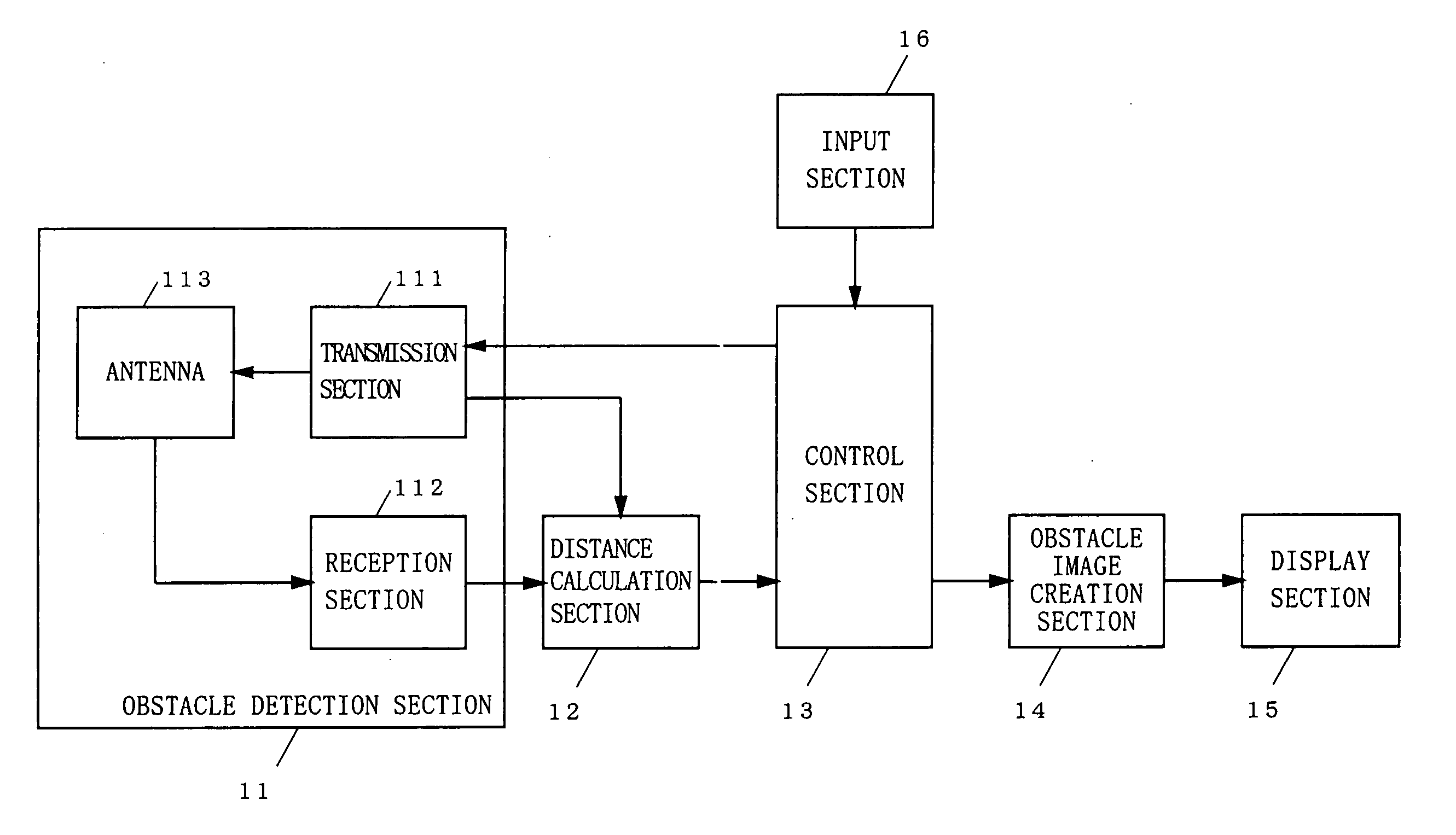
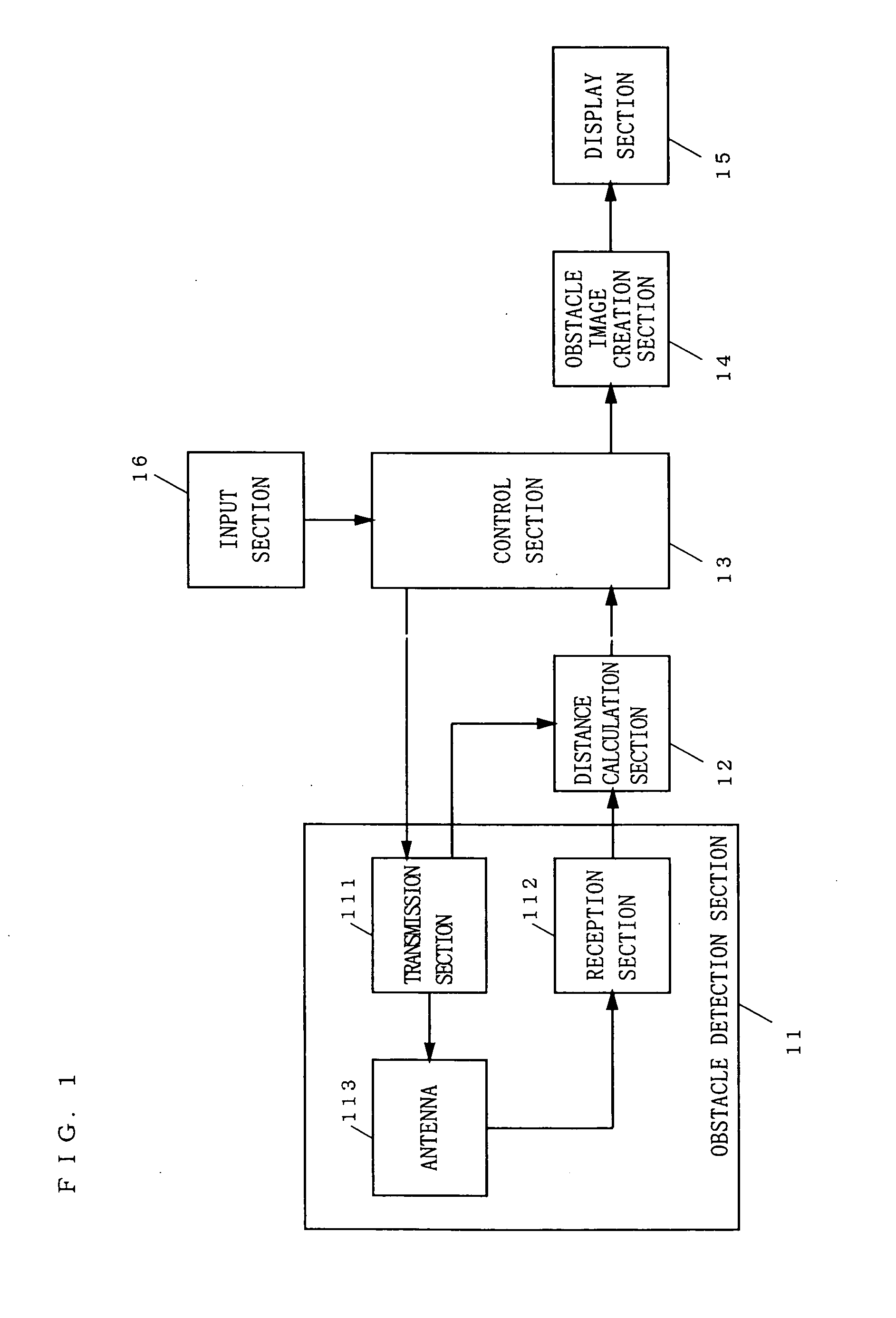
[0059]FIG. 1 is a block diagram illustrating the structure of an obstacle detection device according to a first embodiment of the present invention. In FIG. 1, the obstacle detection device is typically mounted on a vehicle, and includes an obstacle detection section 11, a distance calculation section 12, a control section 13, an obstacle image creation section 14, a display section 15, and an input section 16.

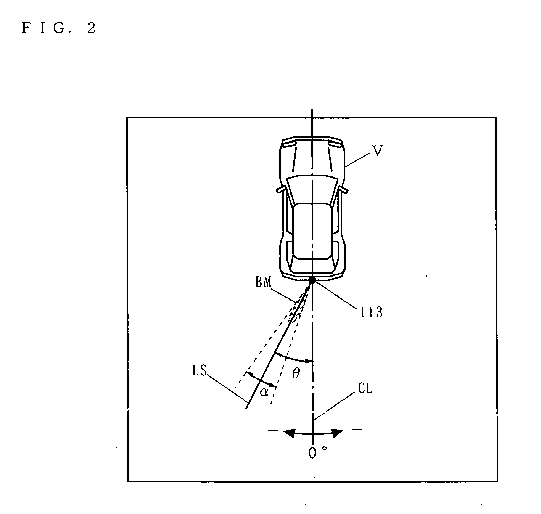
[0060] The obstacle detection section 11 is constituted as a radio-wave radar device which detects an obstacle in the vicinity of a vehicle. Based on the direction in which an obstacle is to be detected, the obstacle detection section 11 is installed at one or more places selected from, for example, the front, sides, and rear of the vehicle. The obstacle detection section 11 emits a beam with a predetermined divergence angle a plurality of times while, changing the direction. Every time the obstacle detection section 11 emits a beam, it receives a reflected wave of the beam r...

second embodiment

[0088] Next, an obstacle detection device according to a second embodiment of the present invention is described. The obstacle detection device according to the present embodiment is characterized in that the obstacle presence lines in the obstacle image is drawn in thicker lines as the distance from the radar to an obstacle becomes shorter. Because of this feature, an obstacle image creation section 14 included in the present obstacle detection device performs different processes from those of the above-described first embodiment.

[0089] Next, with reference to FIG. 11, an operation of the obstacle image creation section 14 is described with respect to the differences from that in the first embodiment. FIG. 11 is a flowchart showing the operation of the present obstacle image creation section 14. The flowchart of FIG. 11 is identical to the flowchart according to the first embodiment (see FIG. 6) except that the process of step S102 is replaced by step S403 and that the process of ...

third embodiment

[0099] Next, an obstacle detection device according to a third embodiment of the present invention is described. The obstacle detection device according to the second embodiment indicates a location of a detected obstacle with an arc the thickness of whose line changes according to the distance from the vehicle. In comparison, the present obstacle detection device is characterized in that a location of a detected obstacle is indicated by a figure (hereinafter referred to as an “obstacle presence area”) ASC having an area, and that the brightness of the figure is changed according to the distance from the vehicle. Because of this feature, an obstacle image creation section 14 included in the present obstacle detection device performs different processes from those of the above-described second embodiment.

[0100] Next, with reference to FIG. 14, processes performed by the obstacle image creation section 14 are described with respect to the differences from those in the second embodime...


PUM


Abstract

An obstacle detection device includes: an obstacle detection section (11) for emitting beams having a predetermined divergence angle consecutively in a plurality of different directions, receiving a reflected wave from an obstacle for each direction, and detecting the obstacle existing within an emission angle range of the beam for the direction; a distance calculation section (12) for calculating a distance representative of an interspace between the obstacle and the vehicle for each direction based on a received signal of the reflected wave for the direction outputted from the obstacle detection section; an obstacle image creation section (14) for creating, as an obstacle image, a figure two-dimensionally developed in the emission angle range of the beam emitted in each direction while treating, as a basis for image creation, the distance calculated by the distance calculation section for the direction, and for creating and outputting image data for displaying the obstacle image; and a display section (15) for receiving the image data created by the obstacle image creation section and displaying an image showing a positional relationship between the obstacle and the vehicle.

Description

TECHNICAL FIELD [0001] The present invention relates to an obstacle detection device, and more specifically to an obstacle detection device to be mounted on a vehicle for detecting and displaying an obstacle in the vicinity of the vehicle. BACKGROUND ART [0002] In a conventional obstacle detection device (hereinafter referred to as a “first obstacle detection device”) a radar that detects an obstacle within a predetermined angular range is used to detect an obstacle behind a vehicle as well as another vehicle on an adjoining traffic lane. If the first obstacle detection device detects an obstacle, it lights an indicator lamp to indicate a direction in which the obstacle has been detected, and displays, in numerals, a distance to the obstacle. [0003] Another obstacle detection device (hereinafter referred to as a “second obstacle detection device”) uses a radar to detect an obstacle in the vicinity of the vehicle and displays an image representing the shape of the detected obstacle. ...

Claims


Application Information

Patent Timeline
Patent Type & Authority Applications(United States)
IPC IPC(8): B62D15/02G01S13/931G05D1/02
CPCB60T2201/10B62D15/027G01S13/931G01S2013/9314G05D1/0238G05D2201/0213G06K9/00812G01S2013/9375G01S2013/9378G01S2013/9385G01S2013/93274G01S2013/93272G01S2013/93271G06V20/586G01S13/93G08G1/16B60R21/00
Inventor WATANABE, YUTAKAYOSHIDA, TAKASHIISHIDA, AKIRA
Owner PANASONIC CORP
Why Eureka
Try Eureka