Peripheral vision reflector

Inactive Publication Date: 2005-10-13
THIR PETER
View PDF8 Cites 9 Cited by
  • Summary
  • Abstract
  • Description
  • Claims
  • Application Information

AI Technical Summary

Benefits of technology

[0025] This patent application discloses a low vision device incorporating any one of the following elements; (1) two reflecting element permanently affixed to the frame in such a way that the mounting point or frame may be physically bent to align the reflecting elements, (2) reflecting elements mounted to the frame along their outside edges, (3) a single unitary frame connecting the two lower reflecting elements, (4) a single lower reflecting

Problems solved by technology

Specifically, macular degeneration results in the deterioration of the macula.
The deterioration of the macula due to macular degeneration typically causes blank or blurry spots in the central field of sight.
Atrophic, or “dry” type, progresses more slowly and has no known cure.
There are few treatments for either type and existing treatments, especially for “dry” type macular degeneration, typically slow the progression of the disease, but do not provide a cure.
These prismatic devices proved expensive to manufacture and were not adjustable.
First, the resistive pivotal attachment does not prevent the relative movement of the reflectors due to the physical forces created by everyday use.
This also limits the area of the periphery of the eye that may be used.
Third, the lack of a connection between the two lower reflecting optical elements, as depicted, creates the potential for these elements to become misaligned with each other.
This requirement for coplanar orientation makes the reflecting optical element difficult to initial

Method used


Image

  • Peripheral vision reflector
  • Peripheral vision reflector
  • Peripheral vision reflector

Examples


Embodiment Construction

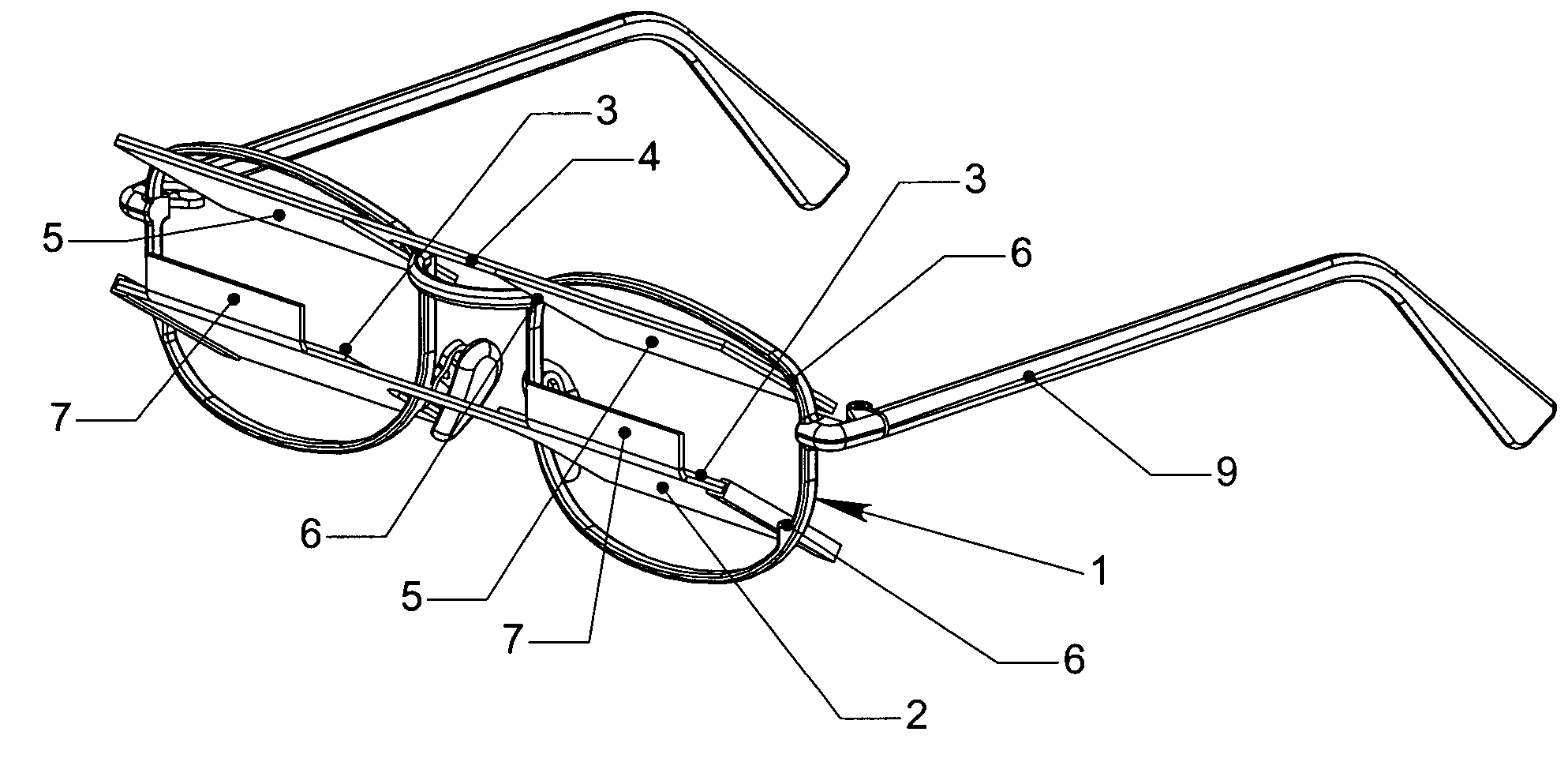
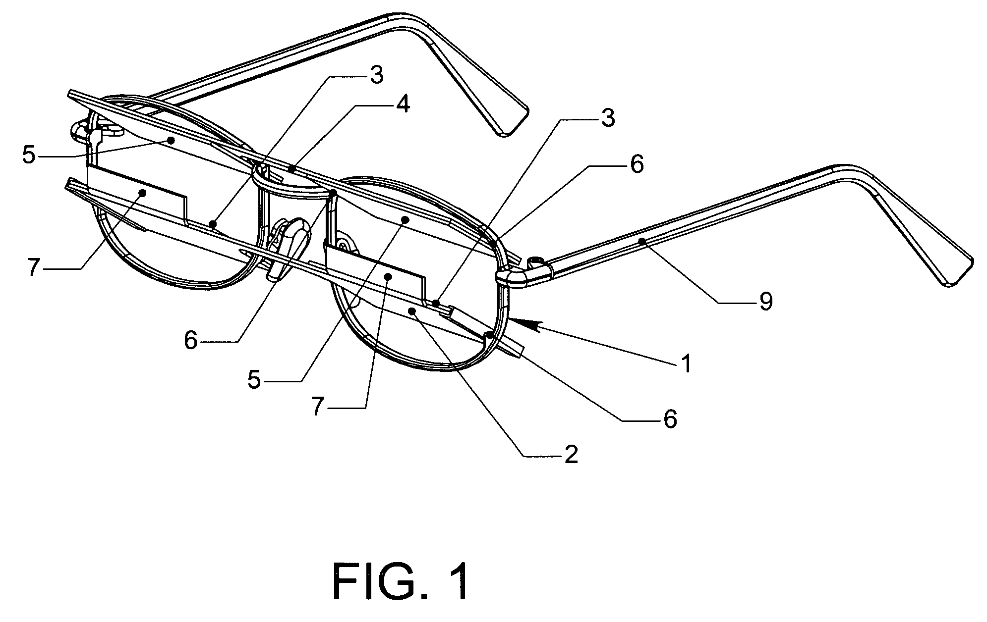
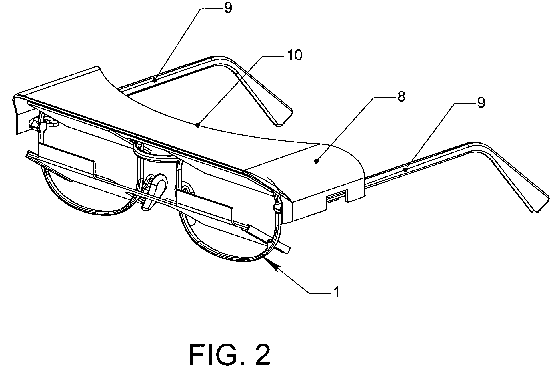
[0047] The Frame (1) is similar to a conventional eyeglass frame. The Lower Reflector Assembly comprises one or two Lower Reflectors (2) mounted to the Lower Reflector Frame (3). Similarly, the Upper Reflector Assembly comprises one or two Lower Reflectors (4) mounted to an Upper Reflector Frame (5). The preferred method for attaching the reflectors to the frame is by use of an adhesive. The upper and lower frames in the preferred embodiment are brazed, welded, or soldered to the frame at the Reflector Assembly Mounting Points. The upper and lower reflector frames may alternatively comprise a frame around the perimeter of the reflectors. The lower reflecting element may comprise a single unified reflecting surface mounted to a lower reflector frame to ensure the coplanar relationship of the left and right reflecting surfaces. In the preferred embodiment, incident light from the source object is reflected off of the upper reflecting element toward the lower reflecting element. The in...


PUM


Abstract

An improved low vision device for macular degeneration victims comprising any one of the following elements; (1) two reflecting elements permanently affixed to the frame, (2) reflecting elements mounted to the frame along their outer edges, (3) a single unified lower reflecting element or frame, (4) a corrective lens pivotally attached to a reflecting element in such a way that it may be removed or rotated away, (5) a shield covering the frame that blocks ancillary light from entering the eye, (6) a shield attached to a reflecting element that blocks light from entering the eye between the upper and lower reflecting elements, and (7) a handheld design featuring two reflecting elements for use with only one eye.

Description

CROSS REFERENCE TO RELATED APPLICATIONS [0001] Not Applicable. FEDERALLY SPONSORED RESEARCH [0002] Not Applicable. SEQUENCE LISTING OR PROGRAM [0003] Not Applicable. FIELD OF THE INVENTION [0004] This invention relates to corrective low vision devices, specifically to improvements of low vision devices for macular degeneration victims. BACKGROUND OF THE INVENTION [0005] Macular Degeneration is a disease affecting roughly 13 million Americans that causes visual impairment. Specifically, macular degeneration results in the deterioration of the macula. The macula is the light sensitive central portion of the retina. A healthy macula allows an individual to discern details in the center of their scope of vision. The deterioration of the macula due to macular degeneration typically causes blank or blurry spots in the central field of sight. Macular degeneration rarely affects peripheral vision. [0006] There are two categories of macular degeneration. Atrophic, or “dry” type, progresses m...

Claims


Application Information

Patent Timeline
IPC IPC(8): G02C1/00G02C7/14G02C9/02
CPCG02C9/02G02C7/14
Inventor THIR, PETER
Owner THIR PETER
Why Eureka
Try Eureka