
Method of producing a corrective spectacle lens and lens blank used for same

Inactive Publication Date: 2005-09-29
THOMAS SA +1
View PDF6 Cites 10 Cited by
  • Summary
  • Abstract
  • Description
  • Claims
  • Application Information

AI Technical Summary

Benefits of technology

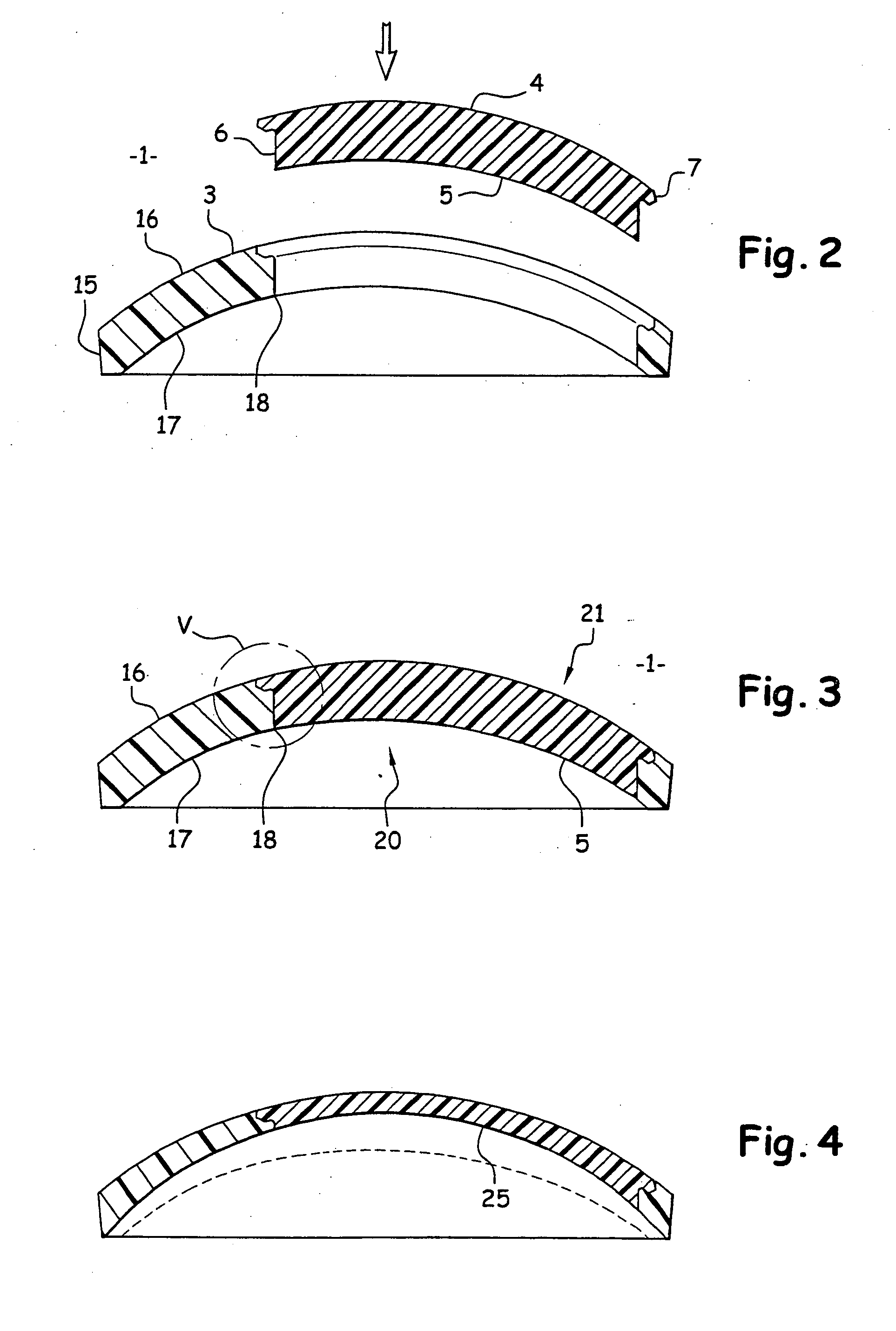
[0019] Machining the inner face of the lens blank is thus realized at the same time on the inner face of the future lens, and also partially on the additional peripheral piece. One thus keeps this continuity of curvature, which enables the use of traditional polishing tools without impairing their abrasive coating, since neither slope nor ridge break is made prior to polishing. This continuity limits or at least reduces the formation of dribbles. It then suffices for the operator to separate the correctly machined corrective lens from the peripheral piece, which may then be eliminated or even recycled.
[0023] One may also foresee that the peripheral piece be obtained by over-molding on the glass blank while keeping at the interface level between the two elements a coating to aid in their final separation.
[0028] In practice, the glass blank and the peripheral part are made of identical materials, specifically in order to avoid the transfer of matter from the peripheral piece to the future corrective lens when the lens blank is subjected to machining and polishing operations. The use of an identical material will also ensure uniform shrinking effects as the two parts of the lens blank cool, or dilation effects during finishing operations.

Problems solved by technology

A problem arises with strongly curved glasses having an important dihedral, since, particularly for myopic corrections, the peripheral thickness of the lens is superior to its thickness at the optical axis level.
One understands that when the extra, peripheral thickness of the lens is very important, the rim of the lens is visible from a distance, which may look unaesthetic.
Furthermore, those who wear corrective glasses, especially sunglasses, generally appreciate that one shall not be able to distinguish sunglasses with corrective lenses from sunglasses with non-corrective lenses.
Realizing tiers of this nature is relatively complex and most frequently requires manual grinding or machining operations, which are incompatible with mass production and usually do not comply with quality criteria, particularly as concerns the repeatability of these operations.
These ridges might lead to problems during machining then polishing operations, which may notably damage the polishing tools as well as the lens.
Indeed, one can observe a degrading of the abrasive polishing coating due to damages caused by the ridges of the relief contour of the future corrective lens.

Method used


Image

  • Method of producing a corrective spectacle lens and lens blank used for same
  • Method of producing a corrective spectacle lens and lens blank used for same
  • Method of producing a corrective spectacle lens and lens blank used for same

Examples


Embodiment Construction

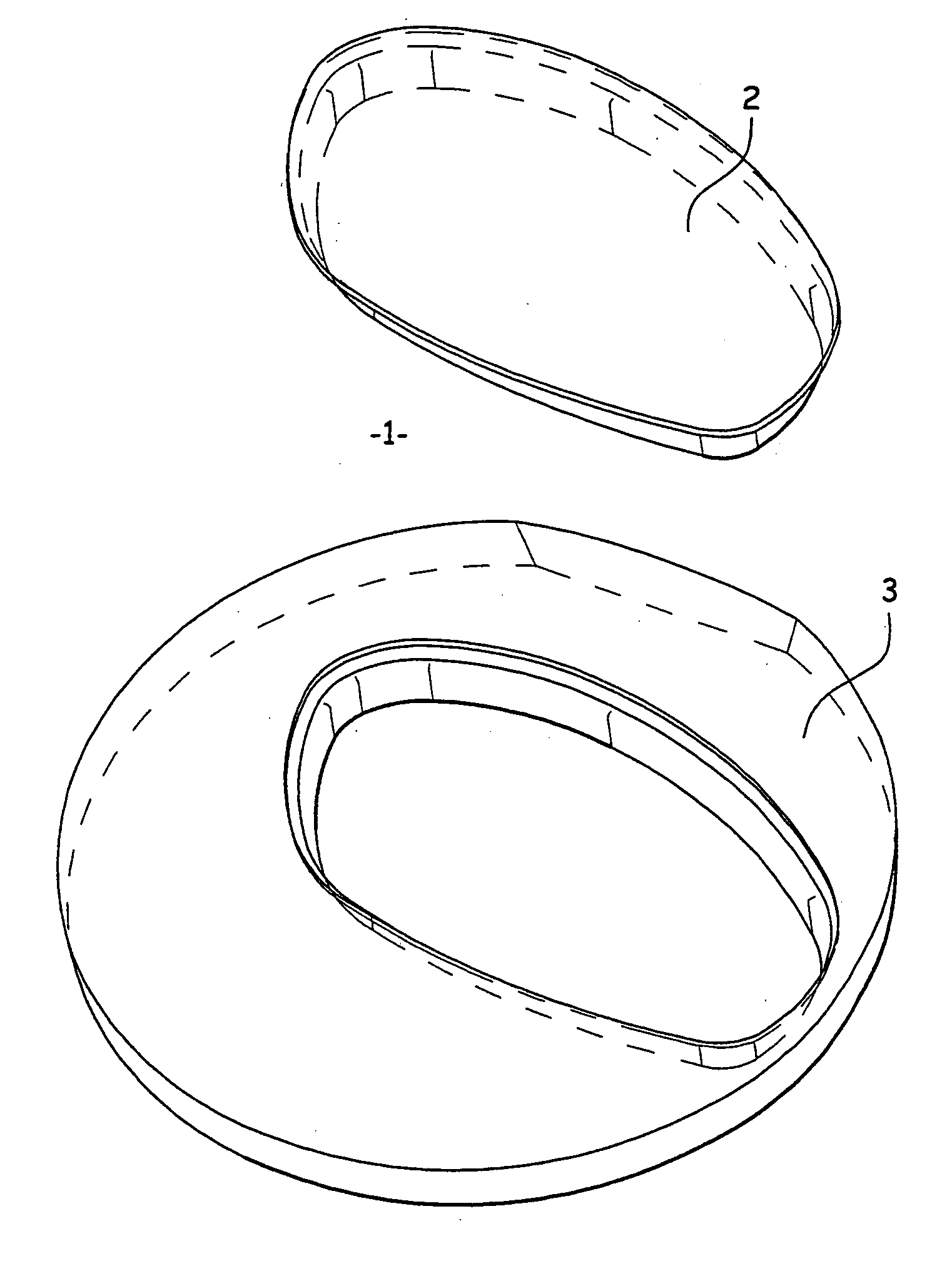
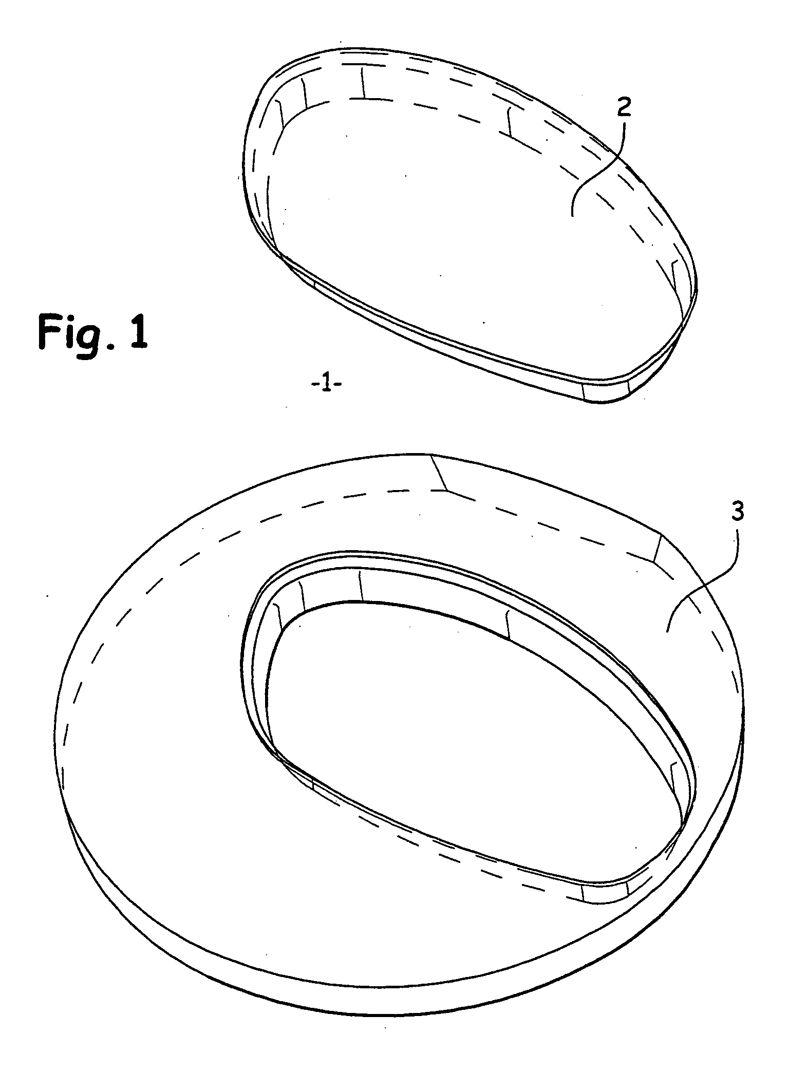
[0036] As previously indicated, the invention permits the manufacture of corrective lenses, particularly lenses to be placed in strongly curved glasses. The lenses arranged in this type of glasses are of highly stressed sphericity, corresponding to the radius of curvature of the outer surface. In the field of glasses industry, the sphericity is usually defined by a base number. Thus, for example, one speaks of an 8-base lens for lenses which radius of curvature of the outer face is between 65 mm to 69 mm.

[0037] This type of lens may be made using the lens blank (1) shown in FIG. 1. Such a lens blank (1) is composed by assembling a glass blank (2) and a peripheral piece (3) into which the glass blank is fitted.

[0038] More precisely, the glass blank (2) is obtained by molding or machining operation, thus defining an outer spherical face (4) as well as an inner face (5), mostly also spherical, before being machined to the desired corrective vision.

[0039] This molding and / or machinin...


PUM

PropertyMeasurementUnit
Radiusaaaaaaaaaa

Abstract

The method of the invention for manufacturing a correctable lens for glasses from an injectable thermo-plastic polymer material, or other moldable polymer, consists in: molding a glass blank (2) provided with the contour of the corrective lens; assembling the lens blank with a peripheral piece (3) having the same internal radius of curvature as that of the glass blank (2), so as to compose a lens blank (1); grinding and polishing the internal face of the lens blank (1) to obtain the desired ocular correction; separating the glass blank (2) from the lens blank to obtain the corrective lens ready for assembly with the frame.

Description

TECHNICAL FIELD [0001] The invention relates to the field of glasses industry, and more particularly to the manufacture of corrective lenses. It aims more specifically at a method for manufacturing corrective lenses for glasses as well as a lens blank used in such a method and intended to facilitate the different manufacturing steps. [0002] The invention is more particularly suitable for the manufacture of corrective lenses to be placed in strongly curved glasses frames. BACKGROUND ART [0003] Most of corrective lenses for glasses are nowadays made from injectable thermo-plastic or polymerizable, resin-based materials, and are obtained from molded or injected lens blanks. This lens blank presents an exterior face, which is generally spherical or progressive, for which the radius of curvature is determined by the curvature of the frame. At this time, one can observe a marked tendency to favor strongly curved glasses with an important dihedral, wrapping around the curvature of the face...

Claims


Application Information

Patent Timeline
IPC IPC(8): B29D11/00G02C1/00G02C7/02G02C13/00
CPCB29D11/00932
Inventor DELERY, MARCTHOMAS, PATRICK
Owner THOMAS SA
Learn More