
Rotational computed tomography system and method

a computed tomography and rotational technology, applied in tomography, instruments, nuclear engineering, etc., can solve the problems of significant heating of all elements, inability to meet the requirements of the system, so as to reduce the rotation load of the conventional ct system, maintain or improve the quantity and quality of the measurement data.

Inactive Publication Date: 2005-10-13
GENERAL ELECTRIC CO
View PDF15 Cites 107 Cited by
  • Summary
  • Abstract
  • Description
  • Claims
  • Application Information

AI Technical Summary

Benefits of technology

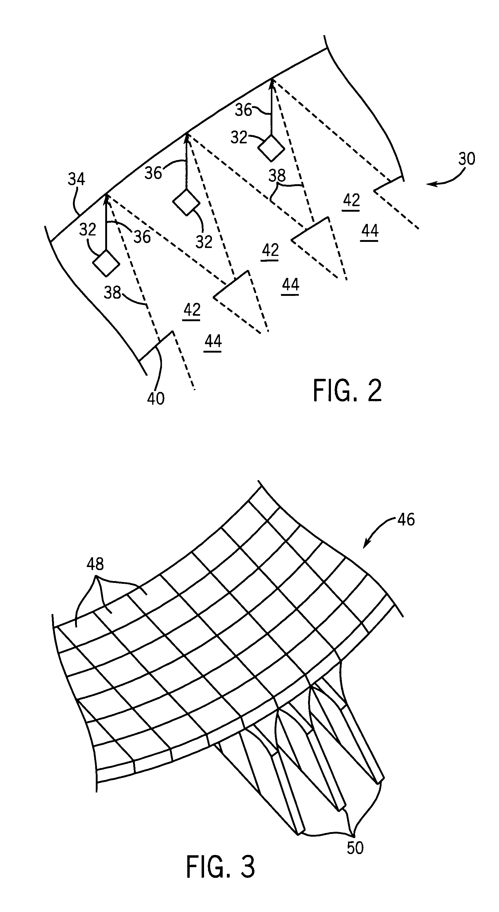
[0006] The present invention provides novel CT configurations and geometries designed to respond to such needs. While presently contemplated applications for the systems include medical diagnostic imaging applications, the new geometries and configurations may find applications well outside the medical diagnostics context, including for part inspection, parcel and package handling and screening, baggage scanning, and so forth. In general, the configurations of the present invention reduce rotation loads of conventional CT systems while maintaining or even improving the quantity and quality of the measurement data. The configurations may include arrangements in which both a source and a detector are rotated, or may call for a rotation of only the detector, or only the source. In certain arrangements of the present technique, ring-like sources or ring-like detectors are employed that may be completely stationary within the system. The present technique is also based upon the provision of distributed X-ray sources that comprise multiple, independently addressable X-ray emitters. In other configurations, the sources are addressable in logical groups, for example pairs or triplets of emitters may be wired together. Unique configurations for these sources are provided that enable the various geometries and configurations. For example, the distributed X-ray sources may form a two-dimensional array. In other configurations the sources form rings around the imaging volume, partial rings around the volume, and lines along the “Z-direction” to use the conventional CT nomenclature. Moreover, the sources and detectors may be comprised of linear or planar sections respectively, which approximate the configurations discussed below.

Problems solved by technology

Conventional CT systems are not, however, without drawbacks.
All of the elements, furthermore, undergo significant heating, requiring extraction of thermal energy during operation.
These various challenges pose extremely difficult problems for system designers and those called upon to maintain the systems.
Moreover, the sheer mass of the source, detector, and associated circuitry and components ultimately limits the rate of rotation of the gantry, and thereby limits the rate and number of view frames that can be collected in a unit of time.

Method used


Image

  • Rotational computed tomography system and method
  • Rotational computed tomography system and method
  • Rotational computed tomography system and method

Examples


Embodiment Construction

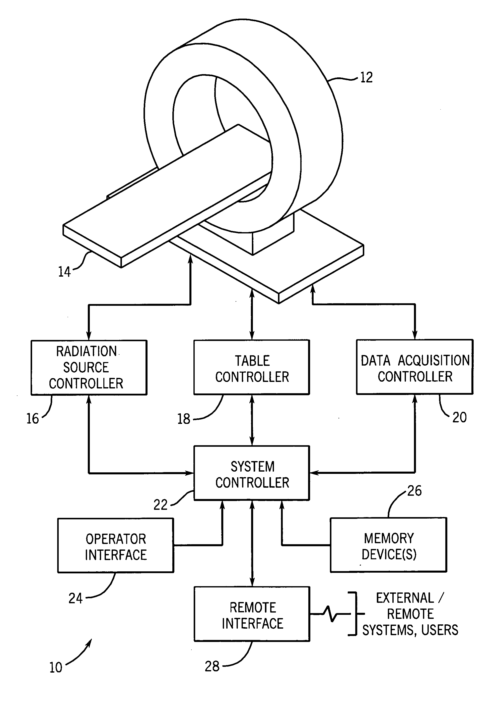
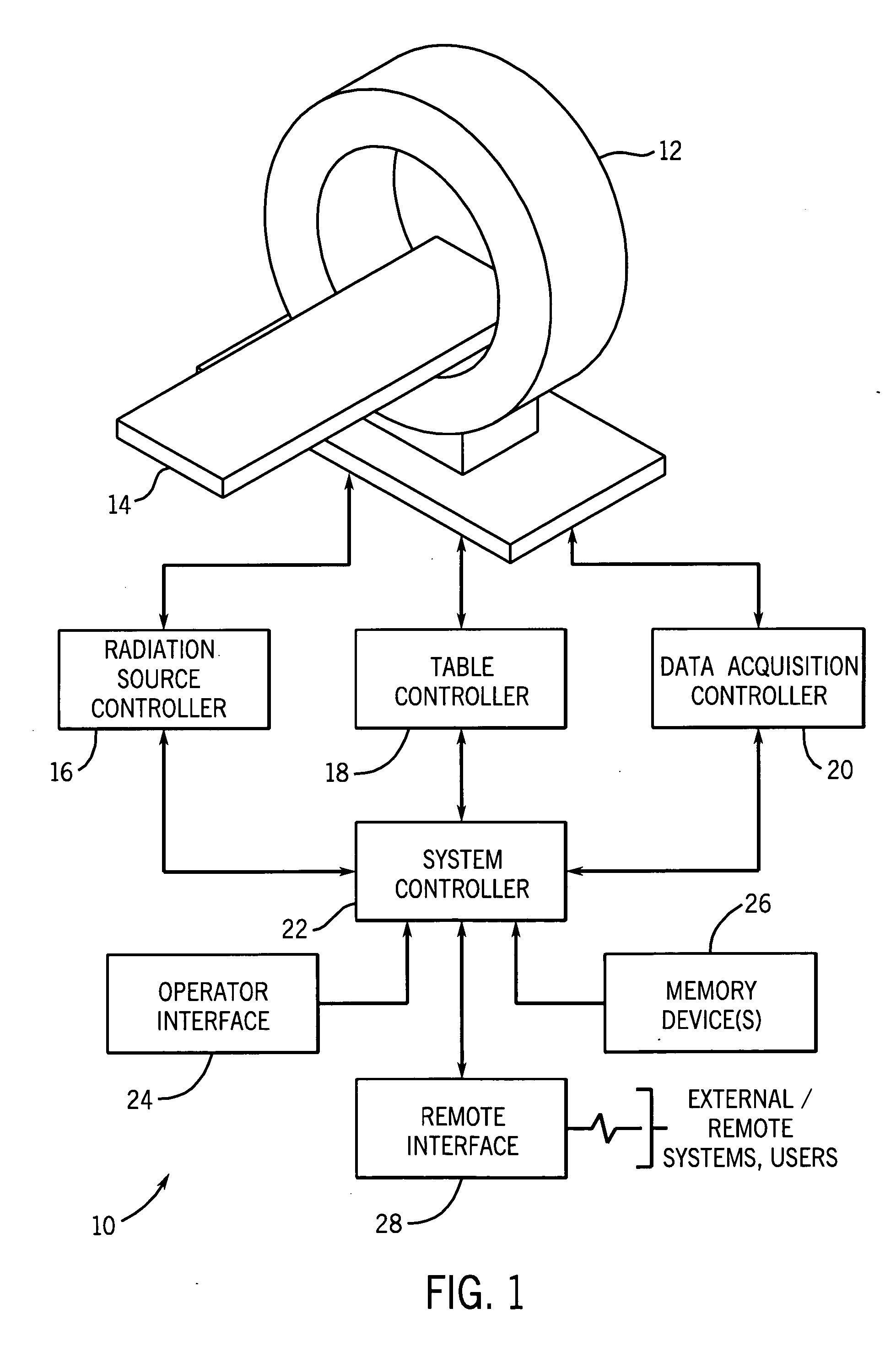
[0019] Turning now to the drawings, referring first to FIG. 1, a computed tomography (CT) system is illustrated and designated generally by reference numeral 10. The CT system 10 comprises a scanner 12 formed of a support structure and internally containing one or more stationary or rotational, distributed sources of X-ray radiation (not shown in FIG. 1) and one or more stationary or rotational digital detectors (not shown in FIG. 1), as described in greater detail below. The scanner is configured to receive a table 14 or other support for a patient, or, more generally, a subject to be scanned. The table can be moved through an aperture in the scanner to appropriately position the subject in an imaging volume or plane scanned during imaging sequences.

[0020] The system further includes a radiation source controller 16, a table controller 18 and a data acquisition controller 20, which may all function under the direction of a system controller 22. The radiation source controller 16 r...


PUM

PropertyMeasurementUnit
volumeaaaaaaaaaa
speedaaaaaaaaaa
Computed tomographyaaaaaaaaaa

Abstract

Geometries and configurations are provided for CT systems in which rotational loading is reduced, permitting higher speeds and lighter structures to be implemented in the systems. In certain embodiments a distributed and addressable rotating radiation source is provided with a rotating detector. In other embodiments a distributed and addressable stationary radiation source is provided with a rotating detector. In yet other embodiments a distributed and addressable radiation source is provided that rotates with respect to a stationary detector. The sources may be ring-like, arcuate and / or lines extending at least in the Z-direction. Sources may include a large number of distributed emitters arranged in lines, arcs and one- or two-dimensional arrays.

Description

BACKGROUND OF THE INVENTION [0001] The present invention relates generally to the field of computed tomography imaging systems. In particular, the invention relates to geometries and configurations for sources and detectors in such systems designed to reduce the rotational load and to enhance speed and imaging abilities of the systems. [0002] Computed tomography (CT) imaging systems have been developed in the past decades and now are prolific in medical diagnostics and other contexts. In general, such systems typically include an X-ray source, such as a conventional X-ray tube, positioned in a diametrically opposed location from a digital detector. The source and detector rotate on a gantry, and the source is triggered repeatedly or is on continuously during rotation to produce beams of X-ray radiation that are directed through a subject of interest and fall onto the detector on the opposite side of a gantry. The emitted radiation is attenuated by features and structures of the subj...

Claims


Application Information

Patent Timeline
Patent Type & Authority Applications(United States)
IPC IPC(8): A61B6/03
CPCA61B6/032A61B6/4014A61B6/035
Inventor BERNARD DE MAN, BRUNO KRISTIAANBASU, SAMIT KUMAREDIC, PETER MICHAELROSS, WILLIAM ROBERTVERMILYEA, MARK ERNEST
Owner GENERAL ELECTRIC CO
Learn More