Attachment system for a sanding tool

a technology of attachment system and sanding tool, which is applied in the field of sanding tools, can solve the problems of unsuitable mating surface, unnecessarily laborious and time-consuming replacement of abrasive discs, and the inability of abrasive articles having a hook and loop attachment system to be attached directly to the back-up pad, etc., and achieves the effect of convenient separation

Active Publication Date: 2005-10-13
3M INNOVATIVE PROPERTIES CO
View PDF28 Cites 40 Cited by
  • Summary
  • Abstract
  • Description
  • Claims
  • Application Information

AI Technical Summary

Benefits of technology

[0022] An advantage of certain embodiments of the invention is that the abrasive article can be readily separated from the conversion pad to allow a user to replace the abrasive article. Another advantage of certain embodiments of the invention is that the abrasive article is uniformly supported by the conversion pad, thereby providing a consistent and uniform abrading surface for abrading the work surface. Yet another advantage of certain embodiments is that the edges of the abrasive article and conversion pad are aligned, thereby allowing a work surface, such as a hardwood floor, to be sanded immediately adjacent an abutting surface, such as a wall.

Problems solved by technology

Such an attachment system, however, made replacement of the abrasive discs unnecessarily laborious and time consuming.
Conventional back-up pads, however, typically include a face that does not provide a suitable mating surface for a hook or loop type of attachment system.
Consequently, abrasive articles having a hook and loop attachment system cannot be attached directly to the back-up pad, but require a back-up pad having a face modified to provide an attachment surface for a hook and loop type attachment system.
Because of the limited finger gripping space between the abrasive article and attachment surface of the back-up pad or conversion pad, however, removal of the abrasive article can be difficult.
In addition, the sanding operation tends to cause the hook and loop attachment to mesh aggressively, making separation more difficult.

Method used


Image

  • Attachment system for a sanding tool
  • Attachment system for a sanding tool
  • Attachment system for a sanding tool

Examples


Embodiment Construction

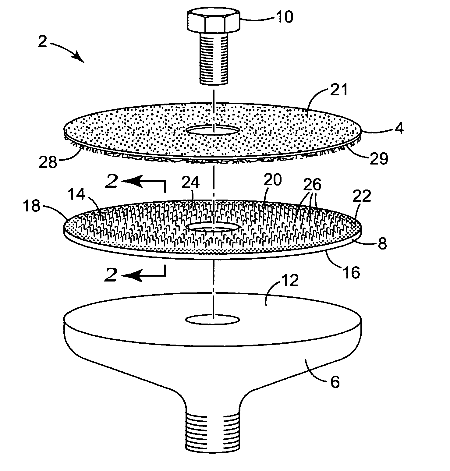
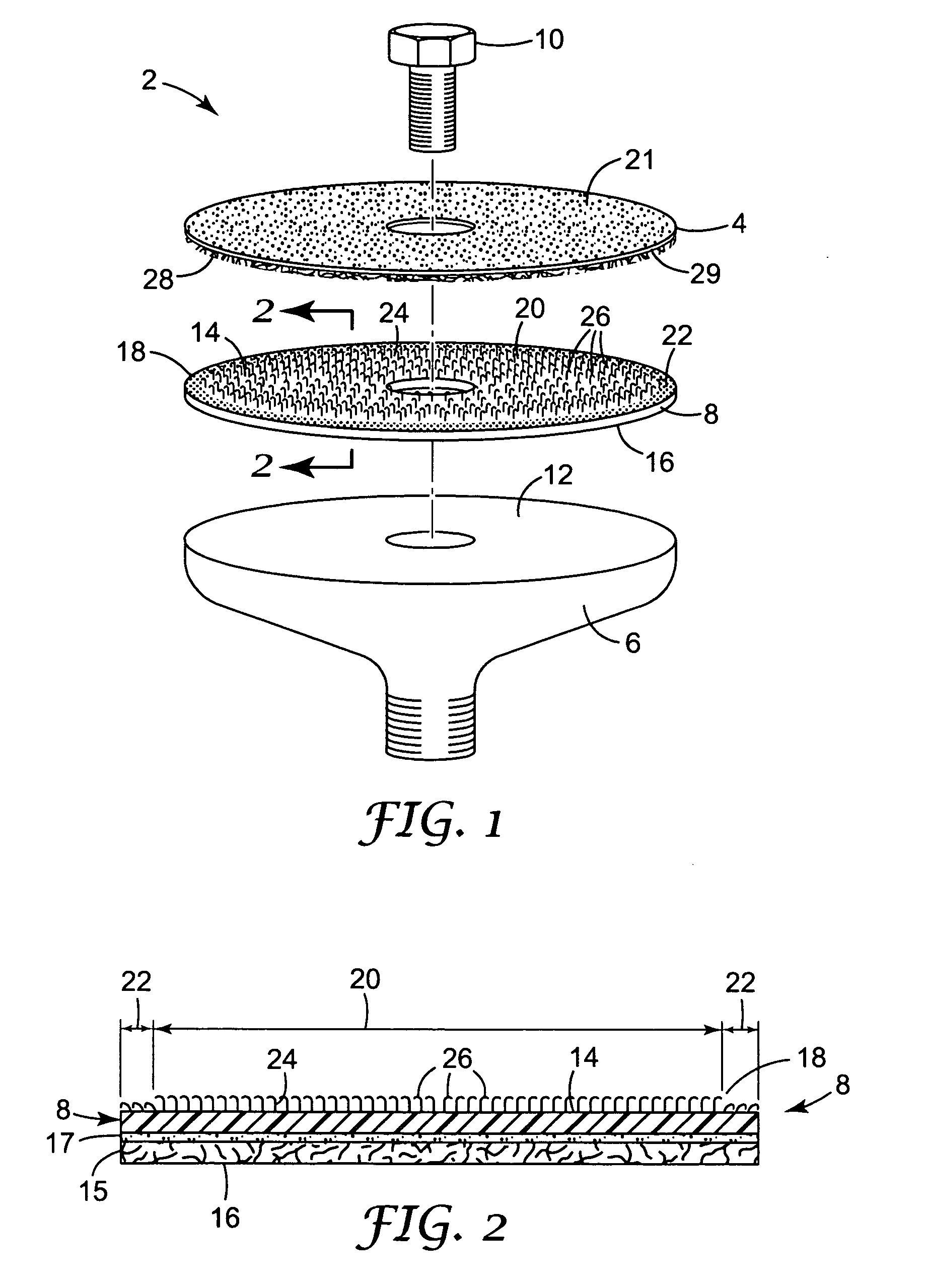
[0039] Referring now to the drawings, wherein like reference numerals refer to like or corresponding parts throughout the several views, FIG. 1 shows an assembly 2 for attaching an abrasive article 4 to a sanding tool (not shown). The assembly 2 includes a back-up pad 6, a conversion pad 8 secured to the back-up pad with a bolt 10, and an abrasive article 4, such as an abrasive sheet or disc, which is attached to the conversion pad 8 in the manner described below.

[0040] The back-up pad 6 has an engagement face 12 against which the conversion pad 8 is placed. Bolt 10 secures the conversion pad 8 against the engagement face 12. The bolt also allows the conversion pad 8 to be removed from the back-up pad 6 and be replaced periodically, if necessary. It will be recognized that other securing means, such as adhesive, may be used to attach the conversion pad 8 to the back-up pad 6. The back-up pad 6 is depicted generically to represent a wide variety of back-up pads and is not limited to...


PUM


Abstract

An attachment system for attaching an abrasive article, such as an abrasive sheet or disc, to a sanding tool includes an article having a first major surface including an attachment region with attachment material for attachment with an associated mating surface on the sanding tool, and a non-attachment region along at least a portion of an edge of the first major surface forming a sufficiently weak attachment with the associated mating surface to allow a user to grasp the abrasive article and separate the abrasive article from the sanding tool.

Description

FIELD OF THE INVENTION [0001] The present invention relates generally to sanding tools such as edger sanders or random orbit sanders and, more particularly, to an attachment system that allows an abrasive article to be easily attached to or separated from the sanding tool. BACKGROUND OF THE INVENTION [0002] Sanding machines and power tools are commonly used to sand and / or refinish hardwood floors. An edger sander is a power tool used to sand the perimeter region of a floor or any other areas of a floor that cannot be sanded by a larger sanding machine such as a drum or belt type sander. [0003] Edger sanders use abrasive articles, such as abrasive sheets or discs, to strip coatings, level, and smooth scratches from all types of wood flooring prior to applying a coating, such as urethane, to the floor. Abrasive sheets and discs are available in a wide variety of sizes, shapes, and abrasive particle sizes (referred to by grit number). When using abrasive articles in the form of “sheet ...

Claims


Application Information

Patent Timeline
Patent Type & Authority Applications(United States)
IPC IPC(8): B24D9/08
CPCB24D9/085
Inventor FISHER, DANIEL J.
Owner 3M INNOVATIVE PROPERTIES CO
Why Eureka
Try Eureka