

Error handling in an embedded system
a technology of error handling and embedded systems, applied in error detection/correction, instruments, computing, etc., can solve problems such as the collection of event-related error information, and achieve the effect of preventing errors and facilitating problem determination
- Summary
- Abstract
- Description
- Claims
- Application Information
AI Technical Summary
Benefits of technology
Problems solved by technology
Method used
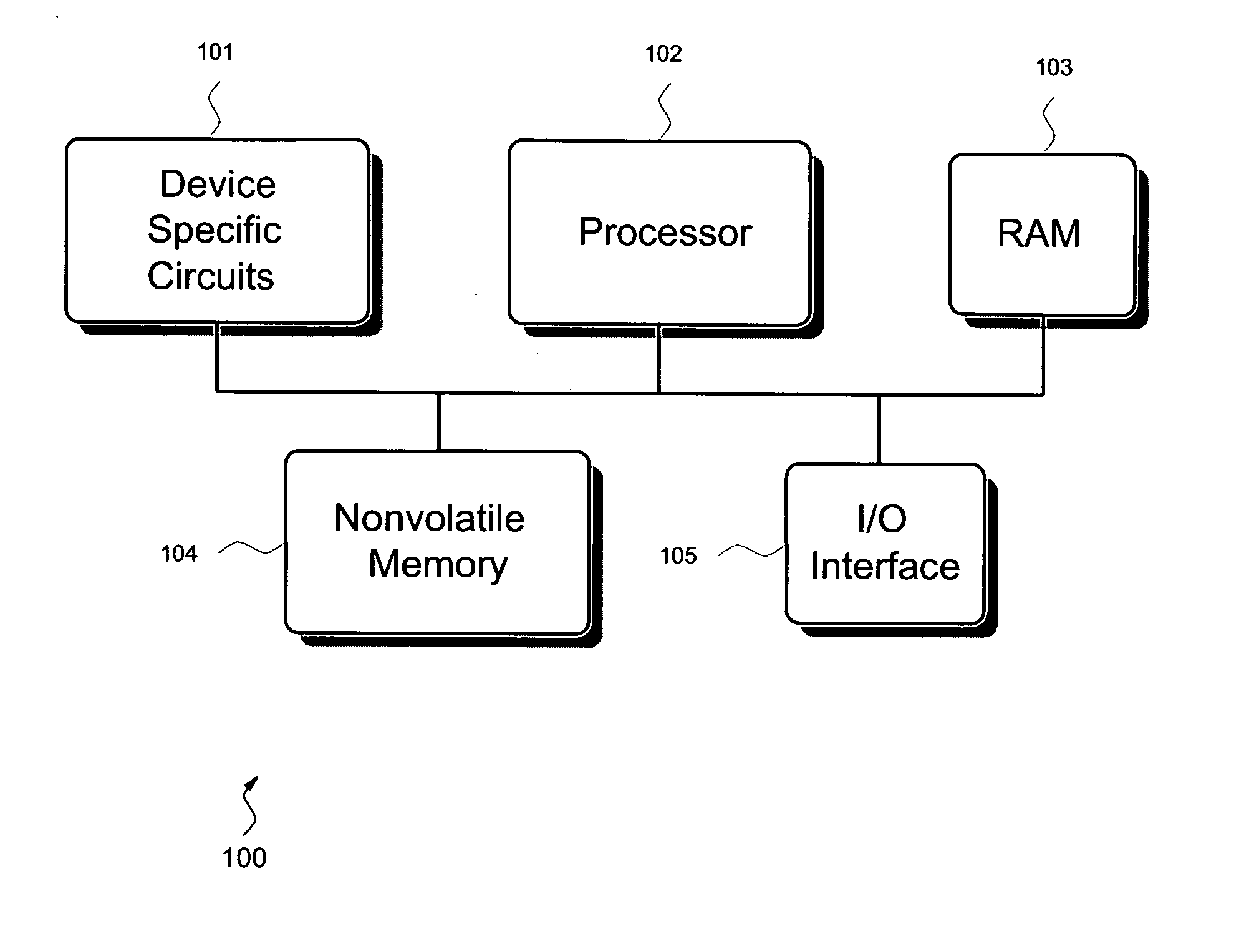
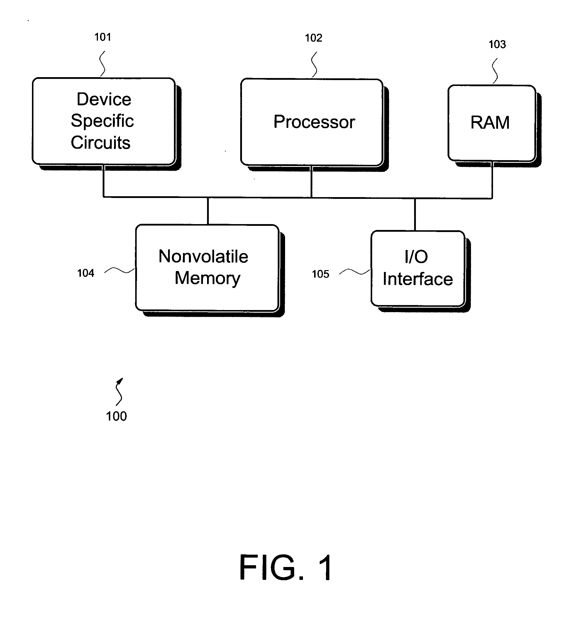
Image

Examples
first embodiment
[0032] The method of the first embodiment is illustrated in the flowchart of FIG. 6. A fatal error is encountered at step 601. The fatal error may comprise any error that requires a reset to continue normal operation of the embedded system. Examples may include, but are not limited to, a processor exception, memory corruption, etc. A memory corruption may comprise memory that contains incorrect, unexpected or random data. A memory corruption may be caused by a code bug, alpha particles, electrical noise, electromagnetic radiation, component failures, etc. A processor exception may comprise an attempt to execute an illegal or unknown instruction, an attempt to access memory off an even address boundary, etc. The processor exception may be caused by a memory corruption, code bug, alpha particles, electrical noise, electromagnetic radiation, component failures, etc. The fatal error may be detected by the embedded system in a number of different ways. For example, the error may be detec...
second embodiment
[0034] The method of the second embodiment is illustrated in the flowchart of FIG. 7. The embedded system powers up or resets at step 701. This may comprise the reset of step 605 (FIG. 6) as discussed above. At step 702 the error flag of step 604 (FIG. 6) is checked. If the error flag does not indicate a previous error as indicated in step 703, then control moves to step 705 where the method of this embodiment ends. If on the other hand, the error flag indicates a previous error as indicated in step 703, then control moves to step 704 where an error status indicator is set. Setting an error status indicator may comprise the display of error information at an operator panel, user interface, or some other human readable display. For example, but without limitation, an error code indicating that the fatal error had occurred may be displayed at an operator panel. Alternatively or additionally, setting an error status indicator may comprise the reporting of error information to another p...
third embodiment
[0036] The method of the third embodiment is illustrated in the flowchart of FIG. 8. The process begins at step 801. At step 802 a check is performed to see if the error flag of step 604 (FIG. 6) indicates that an error has occurred. If an error has not occurred as indicated in step 802, control moves to step 806 where the process ends. This is because there may not be any need to obtain error information if an error has not occurred. Alternatively, this step may be removed because there may not be an error flag, as discussed above. In addition, this step may be removed if it is desired to allow the error information to be obtained more than once after an error has occurred. Referring back to FIG. 8, if on the other hand, a previous error has occurred as indicated in step 802, then control moves to step 803 where error information from step 603 (FIG. 6) is retrieved, collected or sent. For example, an operator may use a diagnostic interface of the embedded system to retrieve the err...
PUM
 Abstract
Description
Claims
Application Information