Average bidirectional flow tube

a flow tube and bidirectional technology, applied in the field of flow meters, can solve the problems of long time required to measure the flow velocity, inability to use the local bidirectional flow tube b>30/b> to measure the average flow rate of fluid, and complicated measurement of flow velocity, etc., to achieve the effect of reducing back pressure and easy measuremen

Active Publication Date: 2005-10-20
KOREA ATOMIC ENERGY RES INST +1
View PDF4 Cites 9 Cited by
  • Summary
  • Abstract
  • Description
  • Claims
  • Application Information

AI Technical Summary

Benefits of technology

[0012] Accordingly, the present invention has been made keeping in mind the above problems occurring in the prior art, and an object of the present invention is to provide a flow meter, which is capable of measuring an average flow rate of a fluid under various flow conditions in a pipe, for example, a single-phase flow and a two-phase flow, and easily measuring the flow rate of a fluid flowing at a low speed by the effect of reducing back pressure, and measuring a flow rate without an additional cooling device in spite of pressure reduction in the pipe. In order to accomplish the above object, the present invention provides an average bidirectional flow tube, including a partition plate provided in a rectangular body, and one or two pairs of pressure impulse lines provided at each of front and rear positions of the partition plate. According to the present invention, the average bidirectional flow tube is capable of measuring an average flow rate of a fluid in the pipe although various types of flow, such as two-phase flow, occur, and preventing a phase change in each pressure impulse line, such that a cooling device is not required.

Problems solved by technology

As described above, the pitot tube 10 is problematic in that the flow velocity of the fluid flowing in the pipe 1 must be repeatedly measured at many positions several times, so that it is complicated to measure the flow velocity and a longer time is required to measure the flow velocity.
That is, the local bidirectional flow tube 30 is not capable of being used to measure the average flow rate of the fluid in the pipe 1.

Method used


Image

  • Average bidirectional flow tube
  • Average bidirectional flow tube
  • Average bidirectional flow tube

Examples


Embodiment Construction

[0025] Hereinafter, embodiments of the present invention will be described in detail with reference to the attached drawings.

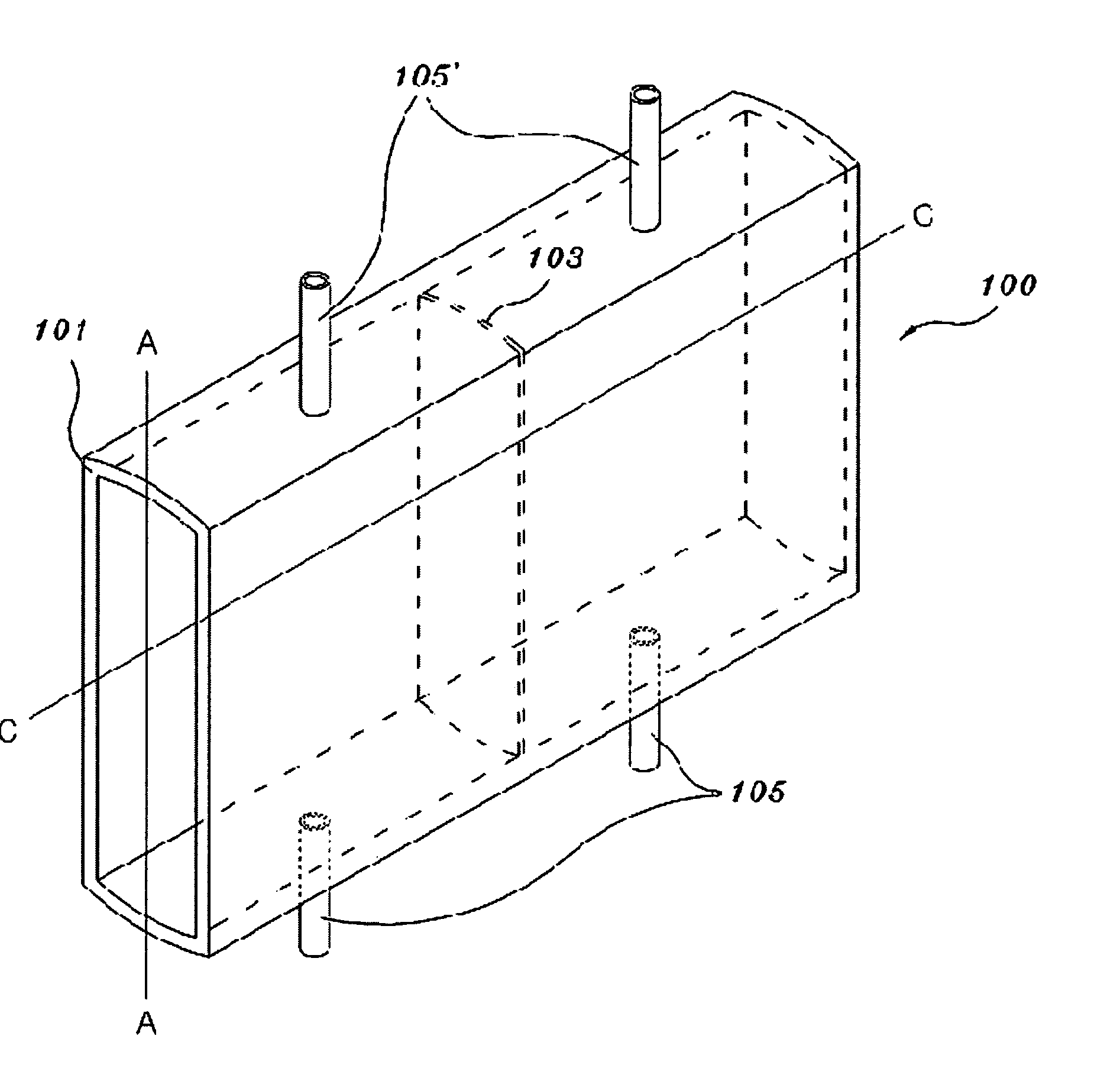
[0026]FIG. 6 shows an average bidirectional flow tube 100, according to an embodiment of the present invention, FIG. 7 is a side sectional view of a pipe 1 in which the average bidirectional flow tube 100 is installed, FIG. 8 is a sectional view taken along the line B-B of FIG. 7, and FIG. 9 is a sectional view taken along the line C-C of FIG. 6. In this case, the same reference numerals are used throughout the different drawings to designate the same or similar components.

[0027] As shown in FIG. 6, the average bidirectional flow tube 100 according to the present invention includes a body 101, a partition plate 103, and two pairs of pressure impulse lines 105 and 105′. Hereinafter, the pressure impulse lines 105 and 105′ might be referred to as an upper pressure impulse line 105′ and a lower pressure impulse line 105, respectively. The body 101 includes two ...


PUM


Abstract

An average bidirectional flow tube, including a body having two side plates and upper and lower plates, a partition plate installed to be perpendicular to the side plates of the body so that front and rear ends of the tube are separated from each other, and two pairs of pressure impulse lines installed at front and rear positions of the partition plate. The upper and lower plates of the body each have a curvature to be in contact with an inner surface of a pipe in which the average bidirectional flow tube is installed, and each of the pressure impulse lines is installed to communicate with an interior of the pipe. Although a two-phase flow occurs in the pipe or the flow of the fluid flowing in the pipe is changed, an average flow rate of a fluid can be measured. Particularly, it is easy to measure an average flow rate of the fluid when the fluid flows at a low speed. Further, even when sudden pressure reduction occurs in the pipe, an additional cooling device is not required. When a two-phase flow occurs in the pipe, the fluid suffers a phase change due to the sudden pressure reduction of the pipe, or a stratified flow occurs due to the two-phase flow in a horizontal pipe, it is unnecessary to displace the average bidirectional flow tube.

Description

BACKGROUND OF THE INVENTION [0001] 1. Field of the Invention [0002] The present invention relates generally to flow meters used to measure a flow rate of a fluid in a fluid system, and more particularly, to a flow meter capable of measuring a mass flow rate of a fluid, even if a single-phase or two-phase flow occurs in a vertical pipe or a stratified flow occurs in a horizontal pipe. [0003] 2. Description of the Related Art [0004]FIG. 1 is a side sectional view of a pipe 1 equipped with a conventional pitot tube 10, with the pitot tube 10 comprising a double pipe (not shown). As shown in FIG. 1, the conventional pitot tube 10 is configured such that a total pressure hole 11 and a static pressure hole 13 are formed at predetermined positions in the double pipe. The pitot tube 10 is installed such that the total pressure hole 11 is opposite to the direction of fluid-stream movement. A total pressure acting on the total pressure hole 11 is a sum obtained by adding a static pressure to ...

Claims


Application Information

Patent Timeline
Patent Type & Authority Applications(United States)
IPC IPC(8): G01F1/40G01F1/46
CPCG01F1/46G01F1/40
Inventor YUN, BYONG-JOKANG, KYOUNG-HOEUH, DONG-JINBAEK, WON-PIL
Owner KOREA ATOMIC ENERGY RES INST
Why Eureka
Try Eureka