Flow control valve with device for indicating the status of a fluid, particularly for gas containers

a flow control valve and fluid status technology, applied in the direction of measuring apparatus components, gas/liquid distribution and storage, water mains, etc., can solve the problem of lowering the safety level of using the cylinder to which it is applied, and achieve the effect of convenient availability, high safety and practicality in use, and low cos

Active Publication Date: 2005-10-20
CAVAGNA GROUP
View PDF11 Cites 20 Cited by
  • Summary
  • Abstract
  • Description
  • Claims
  • Application Information

AI Technical Summary

Benefits of technology

[0013] A further object is to provide a valve in which the status indication device is capable of giving an indication of the quantity of fluid contained in the cylinder without requiring the presence of external components, ensuring higher safety and practicality in use.
[0014] A further object is to provide a valve equipped with a device that allows to monitor the status of the system that connects the cylinder on which it is installed to the user devices, again without requiring the presence of additional components in the system.
[0015] A further object is to allow the replacement, if necessary, of the pressure sensing means without requiring complete removal of the flow control valve from the cylinder.
[0016] A further object of the invention is to provide a valve that can be obtained by assembling components that are easily available and low in cost, so as to ensure an advantage on a purely economic level.

Problems solved by technology

However, that type of device protrudes externally from the body of the valve and is therefore exposed to accidental impacts that can compromise its operation, drastically lowering the safety level in using the cylinder to which it is applied.

Method used


Image

  • Flow control valve with device for indicating the status of a fluid, particularly for gas containers
  • Flow control valve with device for indicating the status of a fluid, particularly for gas containers
  • Flow control valve with device for indicating the status of a fluid, particularly for gas containers

Examples


Embodiment Construction

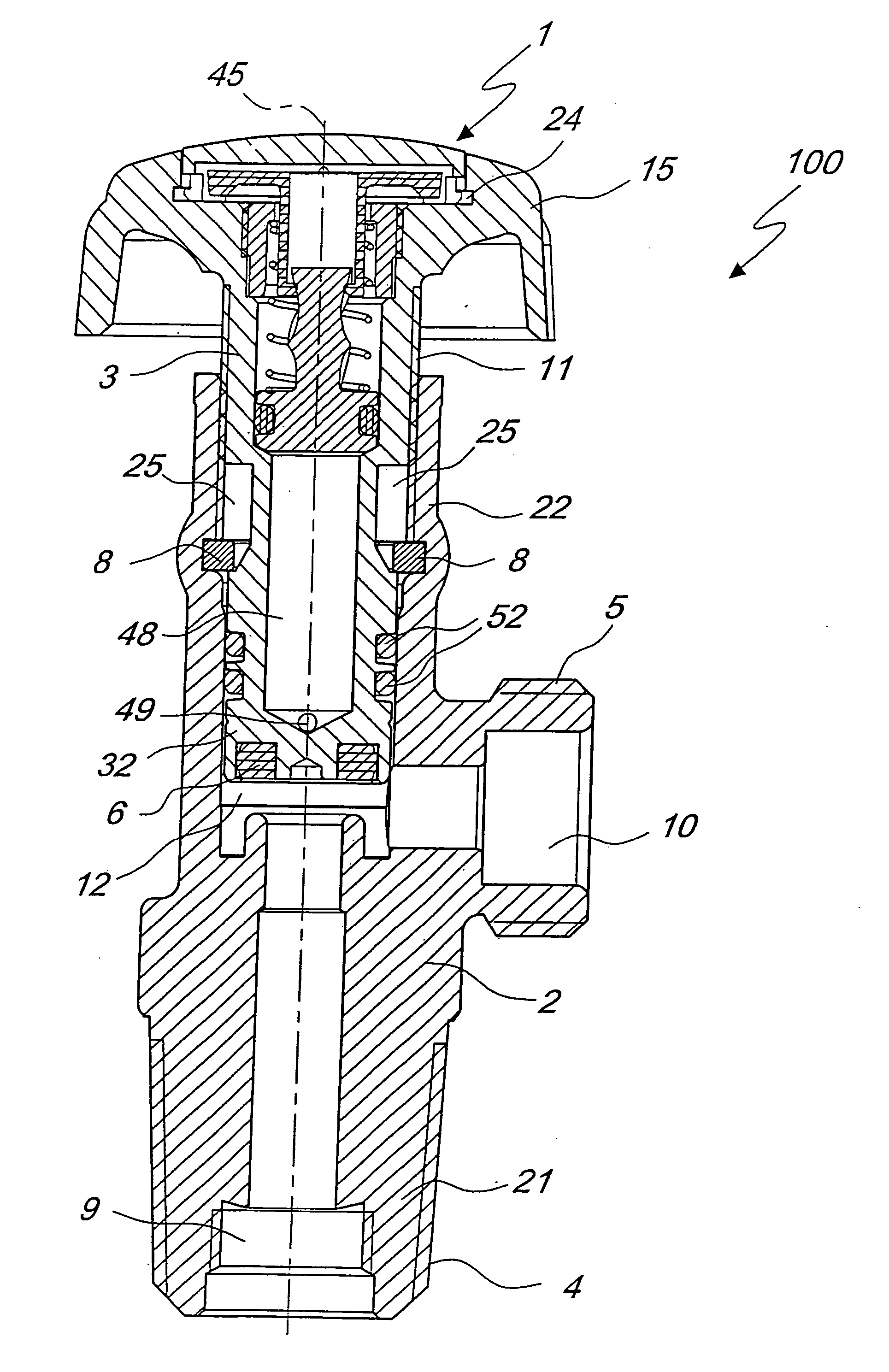
[0024] With reference to the figures cited above, a valve according to the invention, generally designated by the reference numeral 100, includes a body 2, which has an end 21 on which a threaded shank 4 is provided for hermetic coupling to a cylinder, not shown in the figures.

[0025] The body 2 includes a region 5, which provides an hermetic connection to the system for supplying the user devices, which is not visible in the figures.

[0026] A first feed duct 9 is formed inside the shank 4, and a second feed duct 10 is formed inside the region for connection to the user devices; the ducts allow the passage of the fluid that arrives from the cylinder and is directed to the user devices.

[0027] The ducts 9 and 10 are connected by means of a passage 12, which is formed in the region where they intersect.

[0028] The body 2 has a region 22 inside which a piston 3 is accommodated; the piston forms a movable closure member, which is capable of passing from an open position, in which the du...


PUM

PropertyMeasurementUnit
movementaaaaaaaaaa
transparentaaaaaaaaaa
pressureaaaaaaaaaa

Abstract

A flow control valve with device for indicating the status of a fluid, particularly for gas containers, which includes a body provided with an end on which a threaded shank is provided for hermetic coupling to a gas container, and a handwheel, a gas status indicator device being included within the handwheel, the device including a plunger that is constituted by a head and by a helical stem that is engaged in a cavity of a body that can rotate so that an axial movement of the plunger is matched by a rotation of the rotatable body, which has a visible portion that is marked so as to provide an indication of the status of the plunger, which can move, in contrast with a calibrated spring, between at least one minimum position, in which the head abuts against a shoulder, due to the action of the calibrated spring, and a maximum position, in which the plunger abuts against an end of the rotatable body.

Description

BACKGROUND OF THE INVENTION [0001] 1. Field of the Invention [0002] The present invention relates to a flow control valve with device for indicating the status of a fluid, particularly for gas containers. [0003] 2. Description of the Prior Art [0004] As it is known, conventional cylinders or bottles containing liquefied or compressed gases are equipped with a valve for connecting the cylinder, either directly or by means of pressure reduction units, to the user devices to be supplied. [0005] Those conventional devices allow to separate, when required, the user devices from the cylinder in which the fluid is contained. [0006] In order to have an indication regarding the status of the fluid inside the cylinder, it is possible, by means of a connector, to connect a pressure gauge capable of indicating the level of pressure of the fluid. [0007] However, that type of device protrudes externally from the body of the valve and is therefore exposed to accidental impacts that can compromise ...

Claims


Application Information

Patent Timeline
Patent Type & Authority Applications(United States)
IPC IPC(8): F16K1/30F16K31/60F16K37/00F17C13/02G01L7/02G01L7/16G01L19/10G05D7/01
CPCG05D7/0126G01L19/10Y10T137/8326
Inventor FREDERIKSEN, NEILS
Owner CAVAGNA GROUP
Why Eureka
Try Eureka