
Mounting means for a sensor device

a sensor and mounting means technology, applied in the field of retaining devices for sensors, can solve the problems of increasing large space, and the need to discard the entire bumper at considerable expense, and achieve the effect of improving the quality of mounting of the sensor on the outer part, and reducing the cost of such an outer par

Inactive Publication Date: 2005-10-20
DECOMA GERMANY
View PDF4 Cites 14 Cited by
  • Summary
  • Abstract
  • Description
  • Claims
  • Application Information

AI Technical Summary

Benefits of technology

[0008] The additional member may be mounted inside the opening in the endplate by releasable securing means. Expediently, securing means of this kind may be formed by a film hinge or the like, in the case of a retaining device made of plastic. When the endplate of the retaining device is secured to the inner surface of the part, the additional member, after performing its function of centering the opening of the endplate relative to the opening in the part, can easily be removed from the retaining device by breaking off the film hinges, so that the sensor can then be inserted in the retaining device.
[0019] As a result, the quality of mounting of the sensor on an outer part of a motor vehicle, for example, can be increased at very little cost and in a constantly reproducible manner.

Problems solved by technology

If the centering rod is handled clumsily, the retaining device is not properly centered on the bumper, which means that if the adhesive has already cured too much, the entire bumper has to be discarded at considerable expense.
However, this arrangement of the ultrasonic transducer is disadvantageous in that relatively large housings or openings have to be provided on the bumper to accommodate the ultrasonic transducer, which take up a comparatively large amount of space and may conflict with the design specification because of their size.
The adaptor, which holds the ultrasonic transducer on an outer part of a motor vehicle, is disadvantageous in that to fit the adaptor, the holding plate must first be shaped to fit a surface of the outer part, thereby increasing the cost of such an outer part.

Method used


Image

  • Mounting means for a sensor device
  • Mounting means for a sensor device
  • Mounting means for a sensor device

Examples


Embodiment Construction

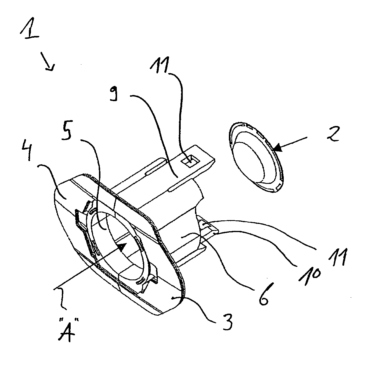
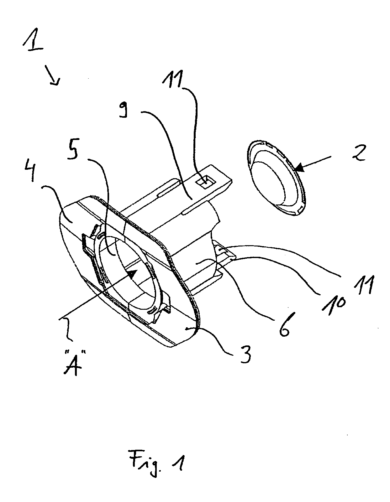
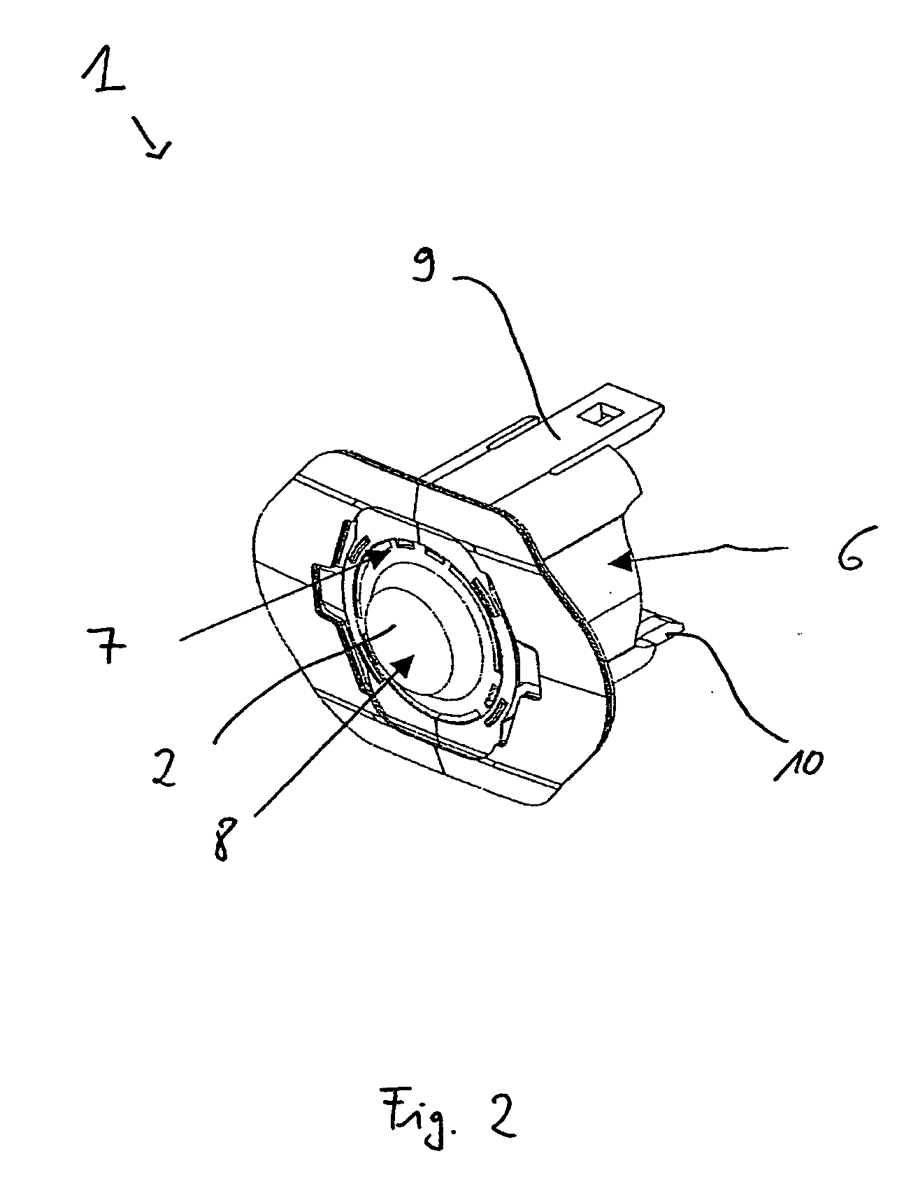
[0024] Referring to FIG. 1, a retaining device 1 according to the invention is depicted along with an additional member 2. The retaining device 1 includes an endplate 3 with a front end face 4. An opening 5 is formed in a central region of the endplate 3. On a rear end face of the endplate 3, opposite the front end face 4, a housing 6 is formed around the opening 5. The housing 6 extends perpendicular to the plane of the endplate 3 away from the rear end face. In the embodiments shown, the housing 6 is circular and correspondingly the housing 6 has a circular cross-section.

[0025] The retaining device 1 is injection molded from a thermoplastic material, which results in reasonable manufacturing costs. An example of such a thermoplastic material is polyamide. However, any other suitable thermoplastic material may be used to produce the retaining device 1. Alternatively, it is also possible to make the retaining device 1 from a duromeric molding composition, e.g., a PUR system.

[0026]...


PUM


Abstract

A retaining device for a sensor is mounted on a part having an opening, in particular, on an outer part of a motor vehicle. The retaining device includes an endplate attachable to an inner surface of the part and having an opening. The retaining device also includes a housing adjacent to the endplate for receiving at least part of the sensor. An additional member is mounted inside the opening in the endplate and includes a projection projecting outwards from the endplate. The additional member can be brought into engagement with the opening in the part such that the opening in the endplate is centrally aligned with respect to the opening in the part.

Description

FIELD OF THE INVENTION [0001] The invention relates to a retaining device for a sensor for mounting on a part, having an opening, and a method of mounting a sensor on such a part. DESCRIPTION OF RELATED ART [0002] In motor vehicle construction, numerous sensors for all kinds of applications are mounted in or on a vehicle body using suitable retaining devices. Systems for determining the distance from other vehicles, which are known for example as Parktronic Systems, generally use ultrasonic sensors that are attached by suitable holders in or on an opening in a bumper. [0003] It is conventional when mounting an ultrasonic sensor on the bumper to attach a retaining device in which the sensor can be held on the reverse of an inner surface of the bumper. For this purpose, the retaining device has an endplate provided with adhesive which is stuck to the inner surface of the bumper. However, before the adhesive on the endplate is brought into contact with the inner surface of the bumper, ...

Claims


Application Information

Patent Timeline
Patent Type & Authority Applications(United States)
IPC IPC(8): B60R19/48
CPCB60R19/483
Inventor GAU, HARRY
Owner DECOMA GERMANY
Learn More