Jounce bumper

a bumper and tpu cup technology, applied in the field of jounce bumpers, can solve the problem of limiting the expansion of the tpu cup, and achieve the effect of increasing the amount of energy

US20050230891A1Inactive Publication Date: 2005-10-20EDWARDS INDS
7 Cites 27 Cited by

Patent Information

Authority / Receiving Office
US · United States
Patent Type
Applications(United States)
Current Assignee / Owner
Publication Date
2005-10-20
Estimated Expiration
Not applicable · inactive patent

Smart Images

  • Figure 1
    Figure 1
  • Figure 2
    Figure 2
  • Figure 3
    Figure 3
Patent Text Reader

Abstract

An energy absorption device for providing a softer stop arrangement between a pair of components. A compressible bumper is placed into a flexible cup. A ring is place around the flexible cup. Upon application of force between the components, the compressible bumper collapses into the flexible cup and the cup begins to expand radially. The ring prevents the cup from expanding to the point of flattening and provides the device with a definite rigid stop. The device is usable between any two components to prevent collisions between the components up to a certain force between them and is also usable between a strut assembly and a vehicle suspension frame.
Need to check novelty before this filing date? Find Prior Art

Description

[0001] This invention relates to a jounce bumper for motor vehicle suspensions systems either in the strut assemblies or other locations. BACKGROUND OF INVENTION

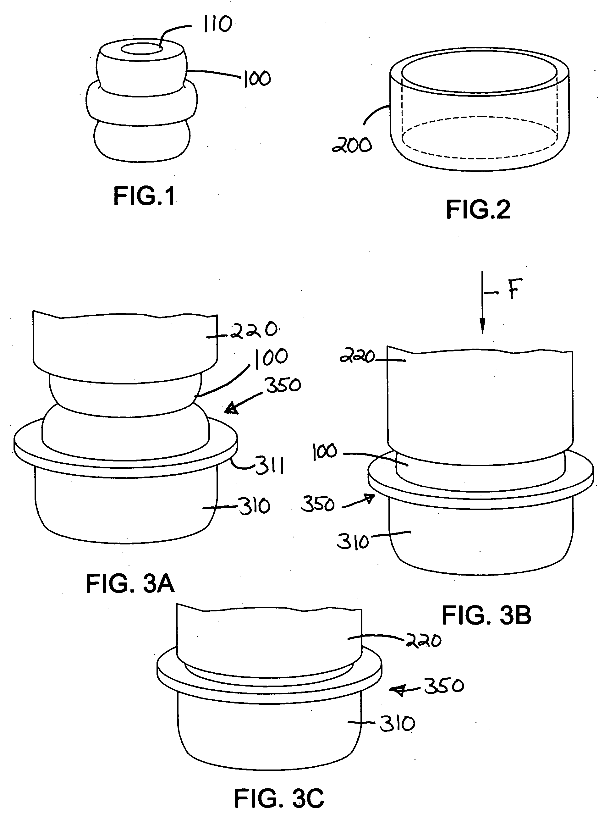
[0002] Microcellular urethane bumpers are used in vehicle suspensions to absorb energy during jounce and to act as a supplemental spring. The bumper 100 has a general appearance as shown in FIG. 1. These could be mounted on a strut assembly, as shown in the U.S. Pat. No. 5,487,535, where the bumper surrounds the piston rod of the strut. A hole 110 through bumper 100 allows for passage of the piston rod. This bumper prevents the cylinder of the strut assembly from impacting heavily the mounting assembly. The bumpers could also be mounted in other locations, as shown in U.S. Pat. No. 5,725,203, where the bumper is free standing to prevent a control arm of the suspension from impacting with the vehicle frame.

[0003] Bumpers can be mounted in a free state or within a rigid cup, as shown in U.S. Pat. No. 6,158,726 which disclose...

Examples

Embodiment Construction

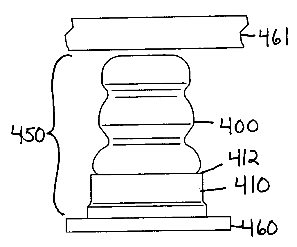
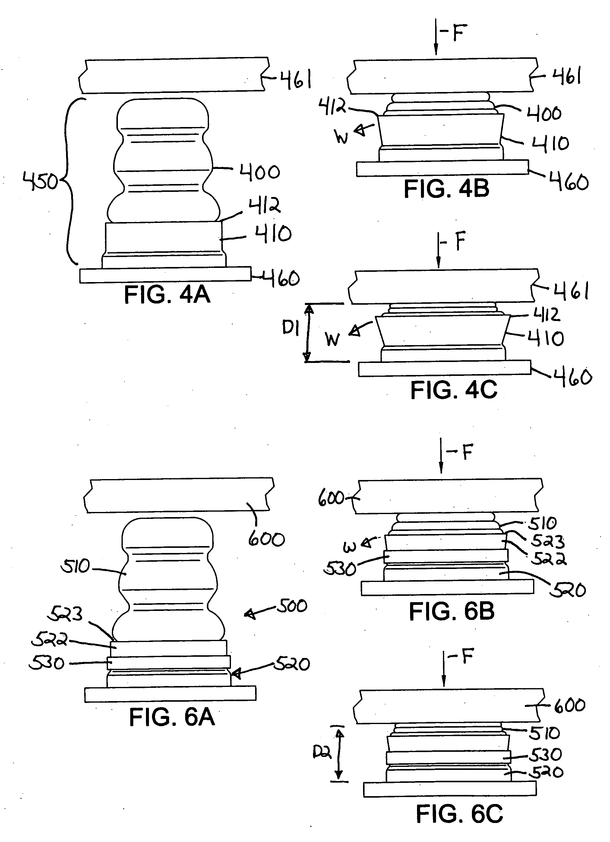
[0020] When the vehicle travels over a bump, a strut assembly collapses to absorb the shock. Upon incurring a force greater than the force the strut can handle, the strut will bottom out, or completely collapse. Bumper assemblies provide a cushion between the cylinder of the strut and the surface to which the strut is attached. In some strut assemblies, a rigid cup is used to mount the bumper, as shown in FIGS. 3A, 3B and 3C. However, these assemblies do not allow for maximum energy absorption and maximum distance travel. On the other hand, a flexible cup in lieu of the rigid cup, while providing increased energy absorption and distance travel, does not provide the system with a definite stop. Accordingly, the preferred embodiment of this invention provides a cup with the energy absorption and distance travel of the flexible cup along with the definite stop of the rigid cup.

[0021] A parts view of the jounce bumper cup according to the invention is shown in FIG. 5A and an assembled ...