Amplification type image pickup apparatus and method of controlling the amplification type image pickup apparatus

a pickup apparatus and amplification technology, applied in the direction of color television details, television systems, radio control devices, etc., can solve the problem of reducing the dynamic range of the image pickup apparatus, and achieve the effect of increasing the dynamic rang

Inactive Publication Date: 2005-10-20
KK TOSHIBA
View PDF12 Cites 16 Cited by
  • Summary
  • Abstract
  • Description
  • Claims
  • Application Information

AI Technical Summary

Benefits of technology

[0004] The object of the present invention is to provide a solid-state image pickup apparatus the dynamic range of which can be increased, and also to provide a method of controlling the solid-state image pickup apparatus.
[0006] In each unit cell, the charge in the charge-accumulating section will be saturated if the light-receiving device receives a large amount of light. This may decrease the dynamic range of the image pickup apparatus. To prevent the dynamic range from decreasing, the charge generated by the light-receiving device during a period and transferred to the charge-accumulating section is limited (that is, a part of the charge is skimmed). The charge that the light-receiving device generates during a later period is added to the charge accumulated in the charge-accumulating section. The unit cell can therefore exhibit different photoelectric conversion characteristics during the first period and the second period, respectively. The first period may be longer than the second period, in which case the dynamic range can be increased.
[0009] Thus, in each unit cell, the signal charge is limited during a horizontal blanking period and signal charges are added during another horizontal blanking period. As a result, the unit cell exhibits different photoelectric conversion characteristics during one-frame period. This makes it possible to increase the dynamic range of the image pickup apparatus.
[0011] That is, the charge is limited and the charges are added in each unit cell during the same vertical blanking period (i.e., the period between two adjacent frame). Hence, not only the dynamic range of the image pickup apparatus can be increased, but also the signals can be read out with sufficient simultaneity.
[0015] In this image pickup apparatus, electric data items corresponding to electric charges generated by the light-receiving device during different periods, respectively, are read through the vertical signal line. Therefore, a composite photoelectric conversion characteristic can be obtained if the electric data items read are added by means of, for example, a signal-processing circuit. In this case, the unit cells can have different photoelectric conversion characteristics merely by varying the charge-generating periods. The dynamic range of the image pickup apparatus can thereby be increased.
[0017] Since the electric data items are read from each unit cell through the vertical signal line during different horizontal blanking periods, the unit cell can exhibit different photoelectric conversion characteristics during one-frame period. This makes it possible to increase the dynamic range of the image pickup apparatus.

Problems solved by technology

This may decrease the dynamic range of the image pickup apparatus.

Method used


Image

  • Amplification type image pickup apparatus and method of controlling the amplification type image pickup apparatus
  • Amplification type image pickup apparatus and method of controlling the amplification type image pickup apparatus
  • Amplification type image pickup apparatus and method of controlling the amplification type image pickup apparatus

Examples


first embodiment

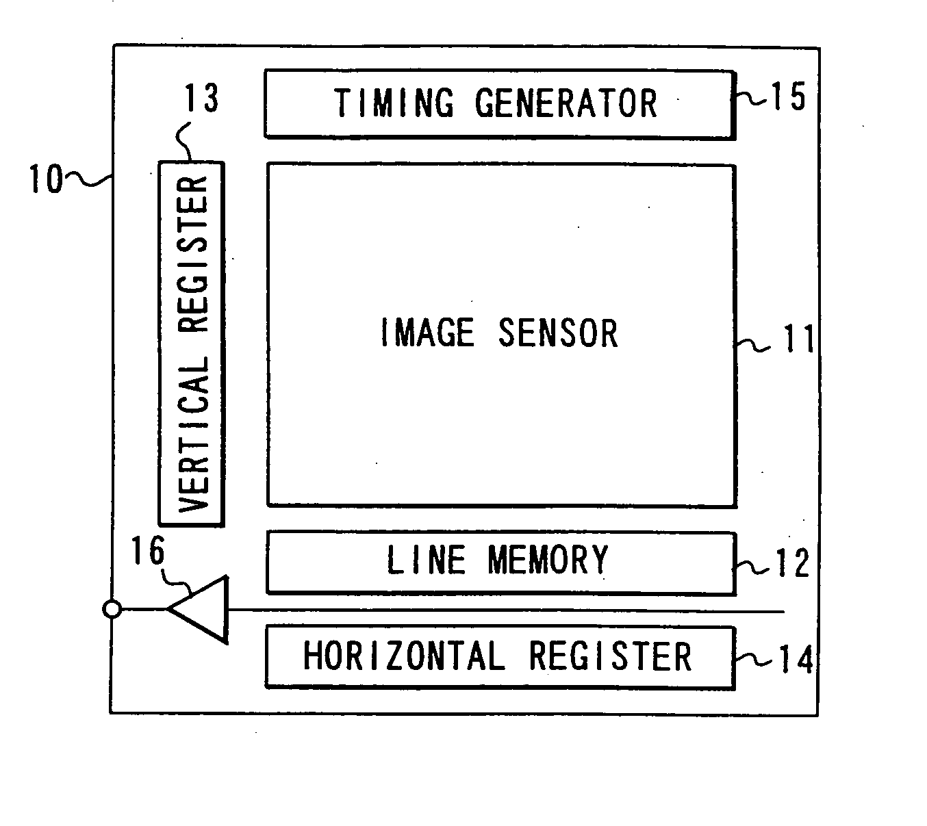
[0041]FIG. 1 is a block diagram showing the main section of a typical solid-state image pickup apparatus of amplification type, which is the first embodiment of the invention.

[0042] As FIG. 1 shows, the image pickup apparatus comprises an image sensor 11, a line memory 12, a vertical register 13, a horizontal register 14, a timing generator 15, and an on-chip amplifier 16. The components 11 to 16 are provided on the semiconductor substrate 10.

[0043] The image sensor 11 has a plurality of unit cells (not shown) and a plurality of vertical signal lines (not shown). The unit cells are arranges in rows and columns. The vertical signal lines extend along the columns of unit cells. Each unit cell accumulates signal charge representing data (electrical information). The data is read to a vertical signal line when the vertical register 13 outputs a control signal to the unit cell, in response to a timing signal supplied from the timing generator 15. The data, thus read, is stored into the...

second embodiment

[0063] The second embodiment of the invention, which is a solid-state image pickup apparatus of amplification type, will be described with reference to the timing charts of FIGS. 7 and 8. The second embodiment is designed for use in electronic still cameras having a mechanical shutter each.

[0064]FIG. 7 explains how this solid-state image pickup apparatus operates if the photodiode provided in each unit cell is of incomplete transfer type, such as an np-type photodiode.

[0065] Assume that the image sensor pick up an ordinary image and that the unit cells of the image sensor generates signals. In this case, the signals are read from the image sensor in units of frames. After reading the signals from the image sensor, the image sensor is reset, as is required because the photodiodes are of incomplete transfer type, such as np-type photodiodes. The signal charges are thereby extracted from the photodiodes, thus skimming bias charges therefrom.

[0066] After resetting the image sensor, t...

third embodiment

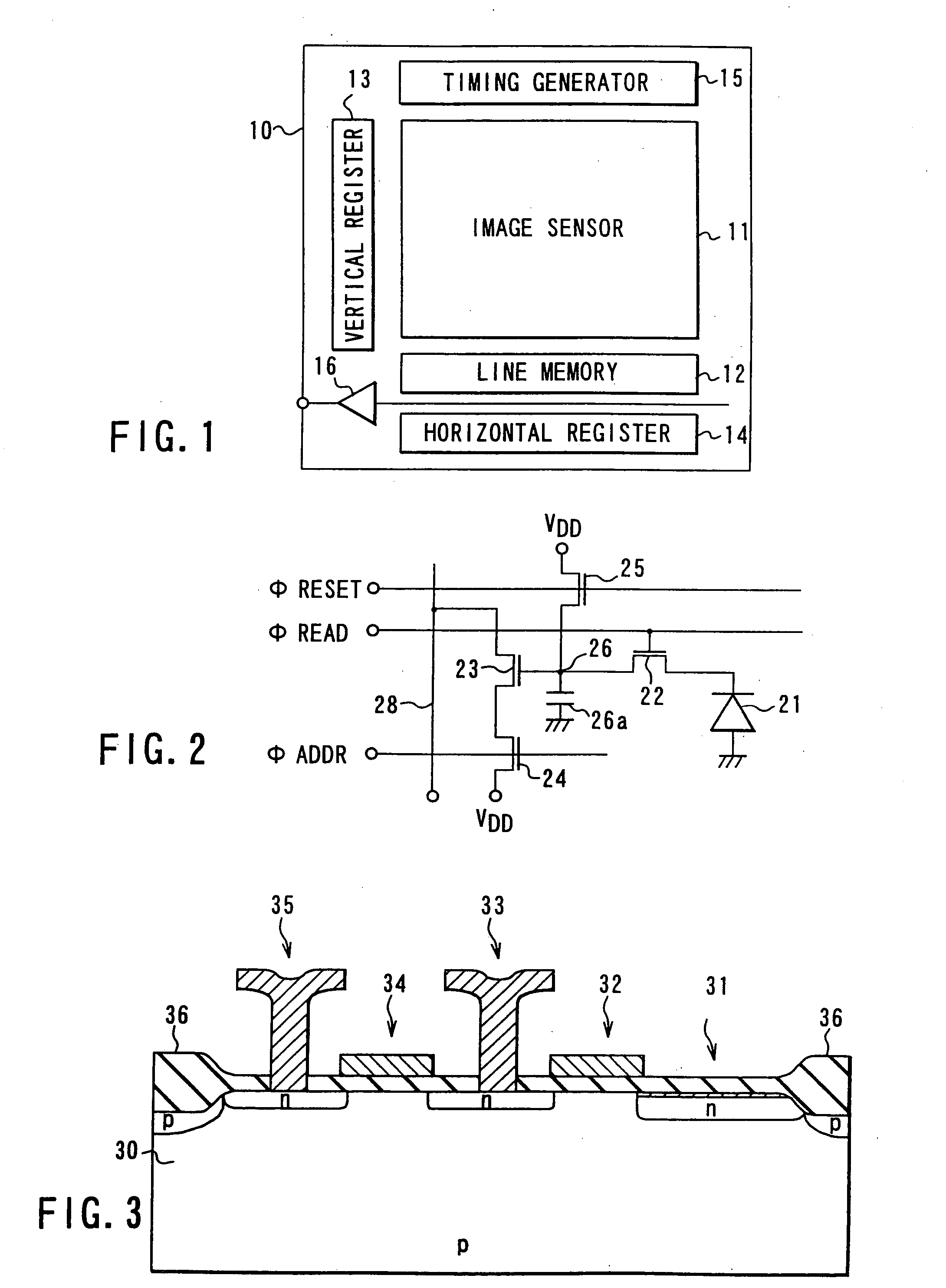
[0069] The third embodiment of this invention, which is also a solid-state image pickup apparatus of amplification type, will be described with reference to the timing charts of FIG. 9. The unit cells of the image sensor incorporated in the third embodiment have a structure similar to the one depicted in FIG. 2.

[0070] As shown in FIG. 9, signals are read from the unit cells of the Xth row and (X+Y)th row during the same horizontal blanking period. During the next horizontal blanking period, signals are read from the unit cells of the (X+1)th and (X+1+Y)th row.

[0071] Assume that T rows of unit cells serve to accumulate signal charges for one frame. In this case, the signal accumulated in any unit cell for the period corresponding to (T-Y) rows is read into the line memory during a horizontal blanking period, and the signal accumulated in the same unit cell for the period corresponding to Y rows is read into the line memory during another horizontal blanking period. These two signal...


PUM


Abstract

An image pickup apparatus comprising an array of unit cells, vertical signal lines, and a control circuit. The unit cells are arranged in rows and columns. Each unit cell has a light-receiving device for receiving light and generating an electric charge corresponding to the light, a charge-accumulating section for accumulating the electric charge generated by the light-receiving device, a transfer device for transferring the electric charge from the light-receiving device to the charge-accumulating section, and a charge-limiting device for limiting the electric charge accumulated in the charge-accumulating section. The vertical signal lines extend along the columns of unit cells, respectively, each for receiving a electric data item corresponding to the electric charge accumulated in the charge-accumulating section of any unit cell of the associated column. The control circuit controls each of the unit cells, causing the charge-limiting device to limit the charge generated by the light-receiving device during a first period and transferred to the charge-accumulating section through the transfer device. The charge generated by the light-receiving device during a second period following the first period and transferred to the charge-accumulating section through the transfer device is added to the electric charge accumulated in the charge-accumulating section.

Description

BACKGROUND OF THE INVENTION [0001] The present invention relates to a solid-state image pickup apparatus, and more particularly to a technique of increasing the dynamic range of a solid-state image pickup apparatus of amplification type. [0002] One of the important features of solid-state image pickup apparatuses is dynamic range. The dynamic range is determined by the signal charge that can be accumulated in each unit cell. The smaller the unit cell, the smaller the capacitance for accumulating the signal charge, and the smaller the saturated signal charge. If the saturated signal charge is small, it will be impossible to increase the dynamic range. [0003] No sufficient measures are taken to increase the dynamic range, in conventional solid-state image pickup apparatuses of amplification type. Consequently, the conventional solid-state pickup apparatuses of this type cannot have high performance. BRIEF SUMMARY OF THE INVENTION [0004] The object of the present invention is to provid...

Claims


Application Information

Patent Timeline
Patent Type & Authority Applications(United States)
IPC IPC(8): H04N5/235H01L27/146H04N5/335H04N5/341H04N5/347H04N5/353H04N5/355H04N5/369H04N5/372H04N5/374H04N5/3745
CPCH04N3/1512H04N5/2355H04N5/235H04N3/1575H04N23/70H04N23/741H04N25/575H04N25/587H04N25/589H04N25/71H04N25/73H04N25/76
Inventor NAKAMURA, NOBUOTANAKA, YORIKOEGAWA, YOSHITAKAOHSAWA, SHINJISUGIKI, TADASHIENDO, YUKIO
Owner KK TOSHIBA
Why Eureka
Try Eureka