Overvoltage protection device

a protection device and overvoltage technology, applied in the direction of emergency protection arrangements for limiting excess voltage/current, circuit-breaking switches, spark gap details, etc., can solve the problems of increasing the risk of integrated circuits being highly endangered and relatively little space in the housing

Inactive Publication Date: 2005-10-20
PHOENIX CONTACT GMBH & CO KG
View PDF0 Cites 53 Cited by
  • Summary
  • Abstract
  • Description
  • Claims
  • Application Information

AI Technical Summary

Benefits of technology

[0024] According to another embodiment of the overvoltage protection device of the invention which is independent of the execution of the second actuating means, the base part of the device has at least one coding element and the overvoltage protection element has at least one corresponding opposing coding element, the coding element or elements and the opposing coding element or elements being arranged in the same manner as the plug contacts of the base part of the device and the connector contacts of the overvoltage protection element as well as the contact element and the mating contact element, each symmetrically to the transverse axis of the overvoltage protection device, so that the base part of the device and the overvoltage protection element can be brought into contact with one another in two arrangements which are turned 180° relative to one another. The execution of the coding element and the opposing coding element is especially advantageous when several overvoltage protection elements can be inserted at the same time into the base part of the device; thus, the overvoltage protection device is a multipin overvoltage protection device. The arrangement of the coding element and of the opposing coding element can then prevent an overvoltage protection element from being incorrectly plugged into the wrong position on the base part of the device.
[0025] Because the base part of the device has a symmetrical connection pattern, the base part of the device can thus be mounted such that connection of the incoming power supply lines to the corresponding terminals is easily possible, and the overvoltage protection element can always be correctly mounted regardless of the alignment of the base part of the device.

Problems solved by technology

This sensitivity has increased to the extent electronic components, especially transistors and thyristors, are being used; in particular, increasingly used integrated circuits are highly endangered by transient overvoltages.
But it is a problem here that, especially in overvoltage protection elements which are made as “protective plugs,” only relatively little space is available in the housing.

Method used


Image

  • Overvoltage protection device
  • Overvoltage protection device
  • Overvoltage protection device

Examples


Embodiment Construction

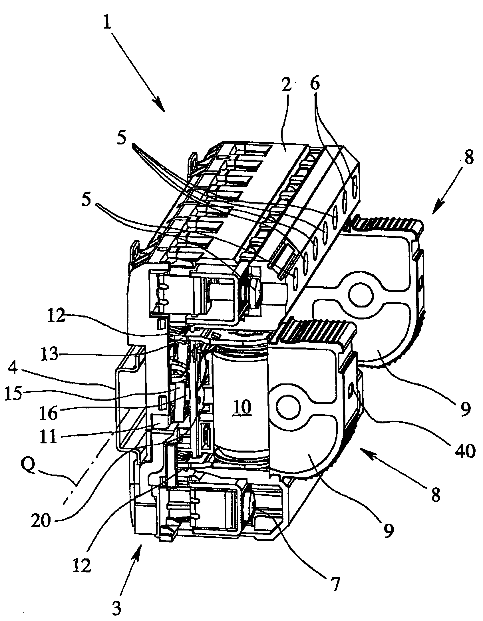
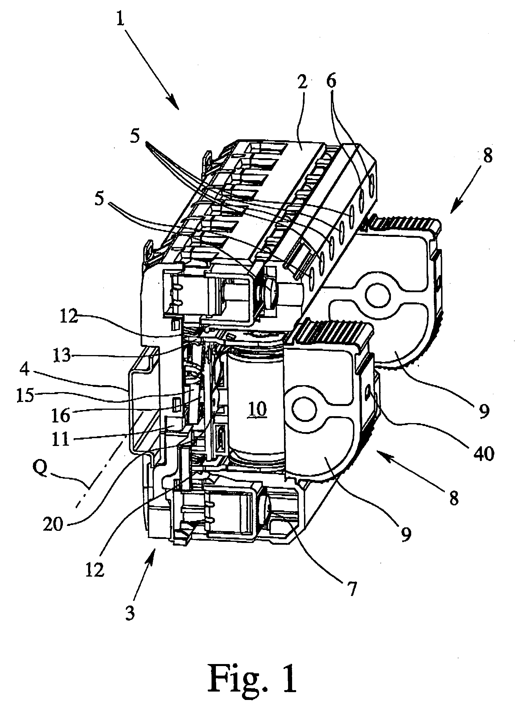
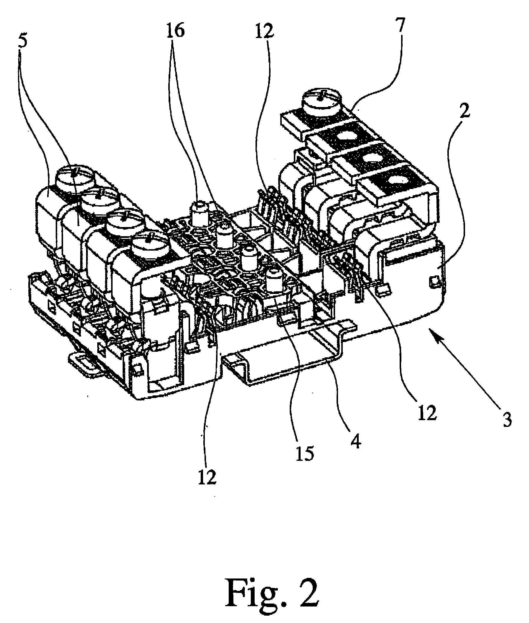
[0034] The figures show an overvoltage protection device 1, with a base part 3 which has a housing 2. In the illustrated embodiments, the base part 3 of the device is essentially U-shaped, and it can be mounted with its bottom on a supporting rail 4. The base part 3 of the device in FIG. 1 on the upper U leg has two terminals 5 for each of the phase conductors and two terminals 6 for the ground conductor. In the bottom U leg of the base part 3 of the device, there are two terminals 7 for the neutral conductor.

[0035] In the embodiment of the overvoltage protection device 1 of the invention which is shown in the figures, the terminals 5, 6, 7 are each made as screw terminals. However, in addition, the terminals 5, 6, 7 can be made equally well as tension spring terminals, direct or leg spring terminals or as insulation piercing connecting devices or quick-connect terminals.

[0036] The arrangement of the terminals 5 for the phase conductors and the terminals 6 for the ground conductor...


PUM


Abstract

An overvoltage protection device for protection of low voltage electrical installations, has a device base part with terminals for phase conductors and ground or neutral conductors and at least one overvoltage protection element, with at least one arrester which is located in a housing. The base part of the device has at least one telecommunications contact which has a switch for remote indication of the state of at least one overvoltage protection element, the base part of the device having plug contacts which are connected to the terminals, and the overvoltage protection element having corresponding connector contacts so that the overvoltage protection element can be plugged onto the base part of the device. The overvoltage protection device is improved by the overvoltage protection element having an optical status display and the optical status display and the switch of the telecommunications contact being actuated via a common mechanical actuating system.

Description

BACKGROUND OF THE INVENTION [0001] 1. Field of Invention [0002] The invention relates to an overvoltage protection device for protection of low voltage electrical installations, having a device base part with terminals for phase conductors (L1, L2, L3) and ground or neutral conductors (PE, N) and of at least one overvoltage protection element, with an arrester which is located in a housing, especially a lightning and / or surge arrester, the base part of the device having at least one telecommunications contact which has a switch for remote indication of the state of at least one overvoltage protection element, and preferably, the base part of the device having plug-in contacts which are connected to the terminals and which are made especially as sockets, and the overvoltage protection element having corresponding connector contacts made especially as plug pins so that the overvoltage protection element can be plugged onto the base part of the device. [0003] 2. Description of Related ...

Claims


Application Information

Patent Timeline
Patent Type & Authority Applications(United States)
IPC IPC(8): H01T1/12H01T4/06
CPCH01T4/06H01T1/12
Inventor SCHIMANSKI, JOACHIMWETTER, MARTINDURTH, RAINERWOSGIEN, JOACHIMBIRKHOLZ, CHRISTIANTEGT, MICHAELTRACHTE, KARSTEN
Owner PHOENIX CONTACT GMBH & CO KG
Why Eureka
Try Eureka