
Systems and methods for fiber distribution hub administration

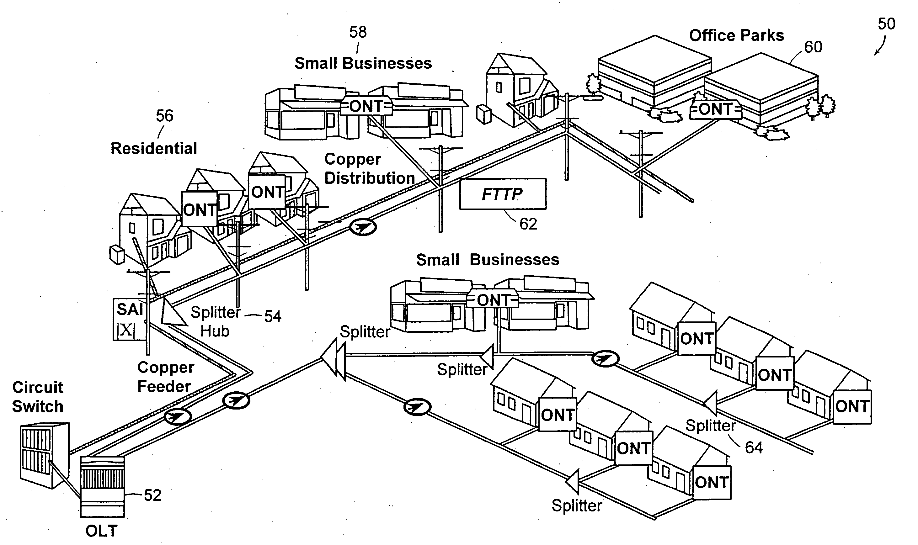
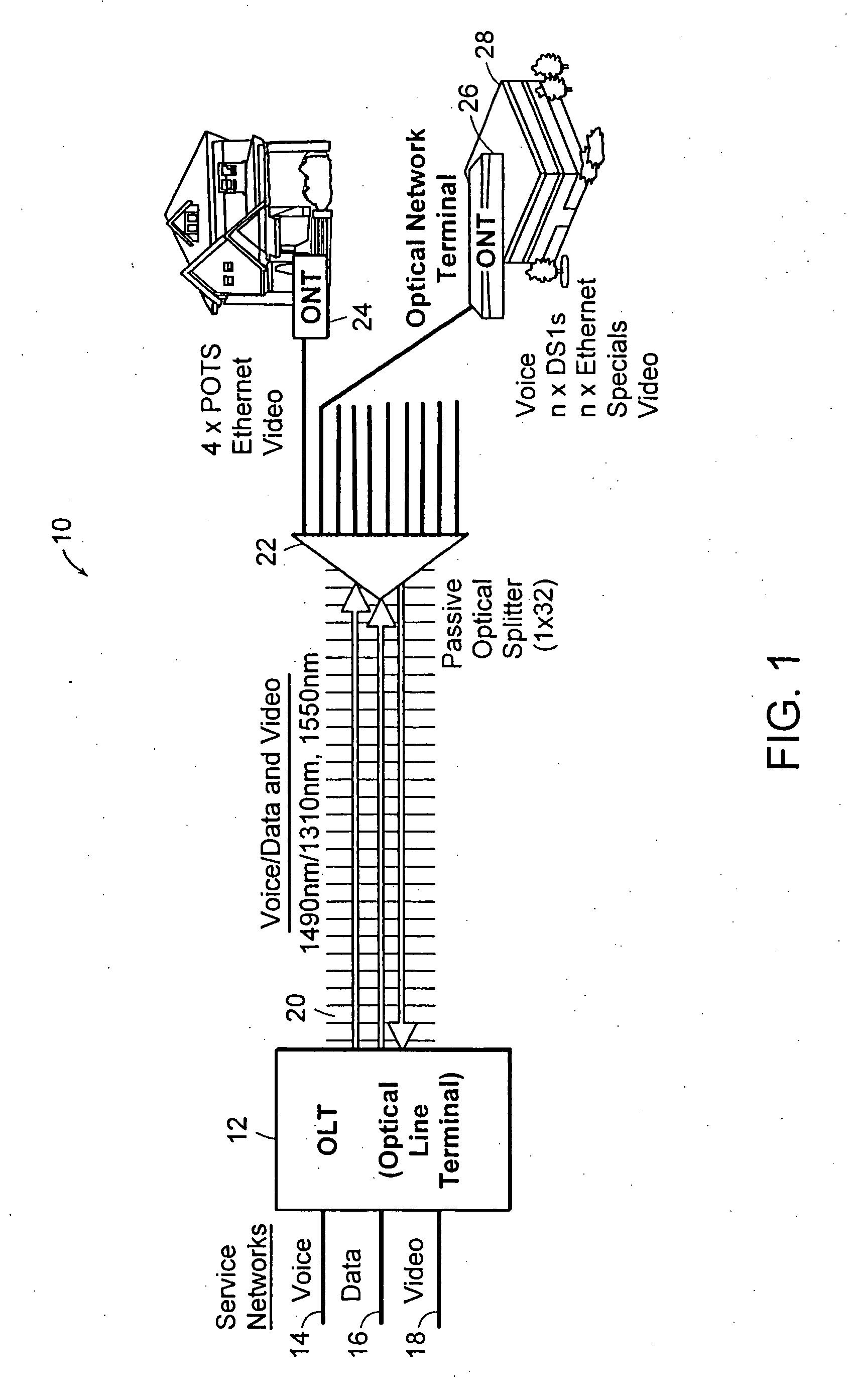
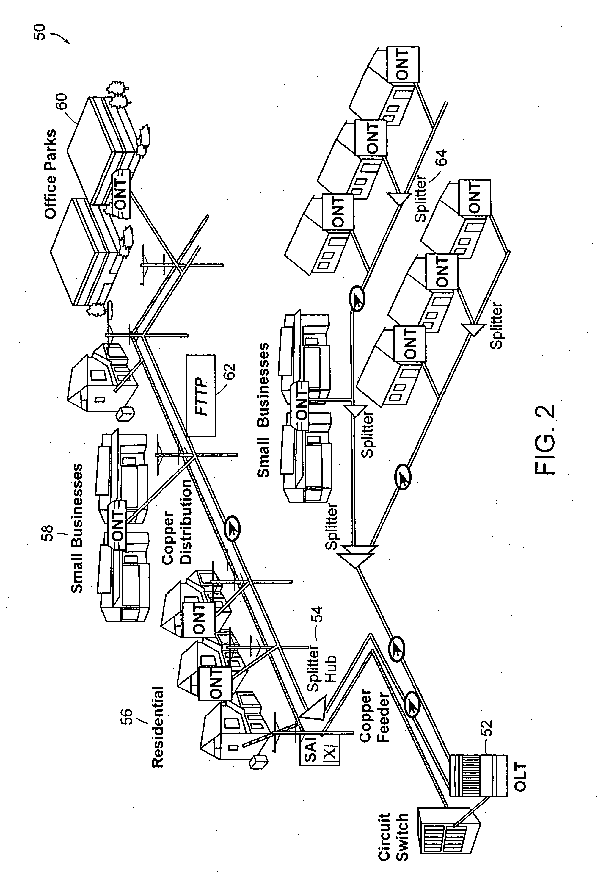
a technology of fiber distribution hub and fiber distribution hub, applied in the direction of fiber mechanical structure, instruments, optics, etc., can solve the problems of inability to protect and organize connectorized ends, delay in service connection, and inability to protect connectorized ends, so as to facilitate incremental deployment of optical splitter modules and facilitate optical signals

Inactive Publication Date: 2005-10-20
COMMSCOPE TECH LLC
View PDF51 Cites 39 Cited by
  • Summary
  • Abstract
  • Description
  • Claims
  • Application Information

AI Technical Summary

Benefits of technology

[0010] In accordance with another implementation, an optical splitter module for use in an optical communications network is provided. The optical splitter module may include an optical splitter configured to split an incoming optical signal into a group of outgoing optical signals. The splitter module may include a faceplate configured to make the group of outgoing optical signals available to a group of pigtails, where each of the group of pigtails is configured to couple a respective one of the group of optical signals to one of a group of subscriber terminations associated with a subscriber termination field. The faceplate may be configured to facilitate incremental deployment of the optical splitter module on a shelf in a manner that facilitates making optical signals from the group of optical splitter modules available to the subscriber termination field.

Problems solved by technology

A problem arises due to the lack of protection and organization of the connectorized ends of the splitter output pigtails.
This method of leaving an exposed optical component such as a high performance connector exposed in an open area leaves it susceptible to damage.
The high performance connectors, if damaged, can cause delays in service connection while connectors are repaired.
Leaving connectorized splitter output pigtails dangling in a cabling trough also exposes them to dirt and debris in the cabling trough.
In addition, the fiber pigtails in the current art are not organized in a manner conducive to rapid service delivery.
In many cases, the splitters may have sixteen or thirty-two output pigtails bundled together making it difficult to find a particular pigtail.
Also the bundle of loose hanging pigtails can easily become entangled causing further delays in service delivery.
The tangles can actually cause congestion and in some cases result in bend induced loss on the pigtails resulting in overall lower system performance.
However, these auxiliary devices tend to take up additional space and often hide the pigtail in an enclosure that can cause further delays in deployment depending on how much time is required to access on the tray or enclosure.
Other methods of storing connectorized pigtails in cable troughs or auxiliary trays may make it difficult to equip splitter output ports with fiber optic terminators.
Finally, current methods tend to result in a disassociation of the splitter module from the splitter output pigtail end.
This usually results because the pigtail, once deployed, gets lost in the midst of other pigtails in the fiber jumper trough.

Method used


Image

  • Systems and methods for fiber distribution hub administration
  • Systems and methods for fiber distribution hub administration
  • Systems and methods for fiber distribution hub administration

Examples


Embodiment Construction

[0026] The preferred embodiments of the present invention are directed to an optical splitter module that is equipped with adapters for storing connectorized optical splitter pigtail ends. Adapters are administratively located on the optical splitter module bulkhead, for example, but not limited to, in octal count arrangements ideally suited to identify splitter ports having sixteen or thirty-two output ports. The adapters in accordance with preferred embodiments are used to store or stage the connectorized ends of the optical splitter for rapid location, identification, easy access and removal of pigtail output ends. In accordance with preferred embodiments, the optical splitter outputs extending from the bulkhead on the module are wrapped back and secured to adapters on the splitter bulkhead. The preferred embodiments also include methods for installing optical splitter modules and associated fixed length output pigtails, storing the connectorized ends of the pigtails in a positio...


PUM


Abstract

A method for configuring an enclosure used in a communications network is described. The method may include providing a group of pigtails. The method may further include routing the group of pigtails circumferentially around a subscriber termination field, where the group of pigtails is associated with an optical splitter module used to convey optical signals to a destination, and where the routing is performed in a manner that does not substantially obstruct access to at least one of a group of subscriber terminations that are associated with the subscriber termination field.

Description

CROSS REFERENCE TO RELATED APPLICATIONS [0001] This application is a continuation of U.S. patent application Ser. No. 10 / 714,814 filed on Nov. 17, 2003, the disclosure of which is hereby incorporated by reference herein.BACKGROUND OF THE INVENTION [0002] In Fiber-to-the-Premises broadband network applications optical splitters are used to split the optical signals at various points in the network. Recent network specifications call for optical splitters to be incorporated in Fiber Distribution Hubs which are re-enterable outdoor enclosures. These enclosures allow easy re-entry for access to optical splitters allowing splitter ports to be utilized effectively and for additional splitter ports to be added on an incremental basis. [0003] In typical applications to date, optical splitters are provided prepackaged in optical splitter module housings and are provided with splitter outputs in pigtails that extend from the module. The splitter output pigtails are typically connectorized wit...

Claims


Application Information

Patent Timeline
Patent Type & Authority Applications(United States)
IPC IPC(8): G02B6/44H04Q1/14
CPCG02B6/4452H04Q1/14H04Q1/021H04Q2201/804H04Q2201/10G02B6/46G02B6/44
Inventor REAGAN, RANDYGNIADEK, JEFFPARSONS, TOMNOONAN, MICHAEL
Owner COMMSCOPE TECH LLC
Learn More