
Video recording apparatus, multiplexing method, picture encoding method, program, and recording medium for variable frame-rate recording

a video recording and frame rate technology, applied in the field of video recording equipment, can solve the problem that the conventional video recording apparatus consumed quite many recording media

Active Publication Date: 2005-10-20
PANASONIC CORP
View PDF9 Cites 23 Cited by
  • Summary
  • Abstract
  • Description
  • Claims
  • Application Information

AI Technical Summary

Benefits of technology

[0010] However, conventional video recording apparatus consumed quite many recording media as they records 60p picture signals resulted from a pull-down process in a VTR, which uses intra-frame compression, where they only need to record Xp picture signals.

Problems solved by technology

However, conventional video recording apparatus consumed quite many recording media as they records 60p picture signals resulted from a pull-down process in a VTR, which uses intra-frame compression, where they only need to record Xp picture signals.

Method used


Image

  • Video recording apparatus, multiplexing method, picture encoding method, program, and recording medium for variable frame-rate recording
  • Video recording apparatus, multiplexing method, picture encoding method, program, and recording medium for variable frame-rate recording
  • Video recording apparatus, multiplexing method, picture encoding method, program, and recording medium for variable frame-rate recording

Examples


embodiment 1

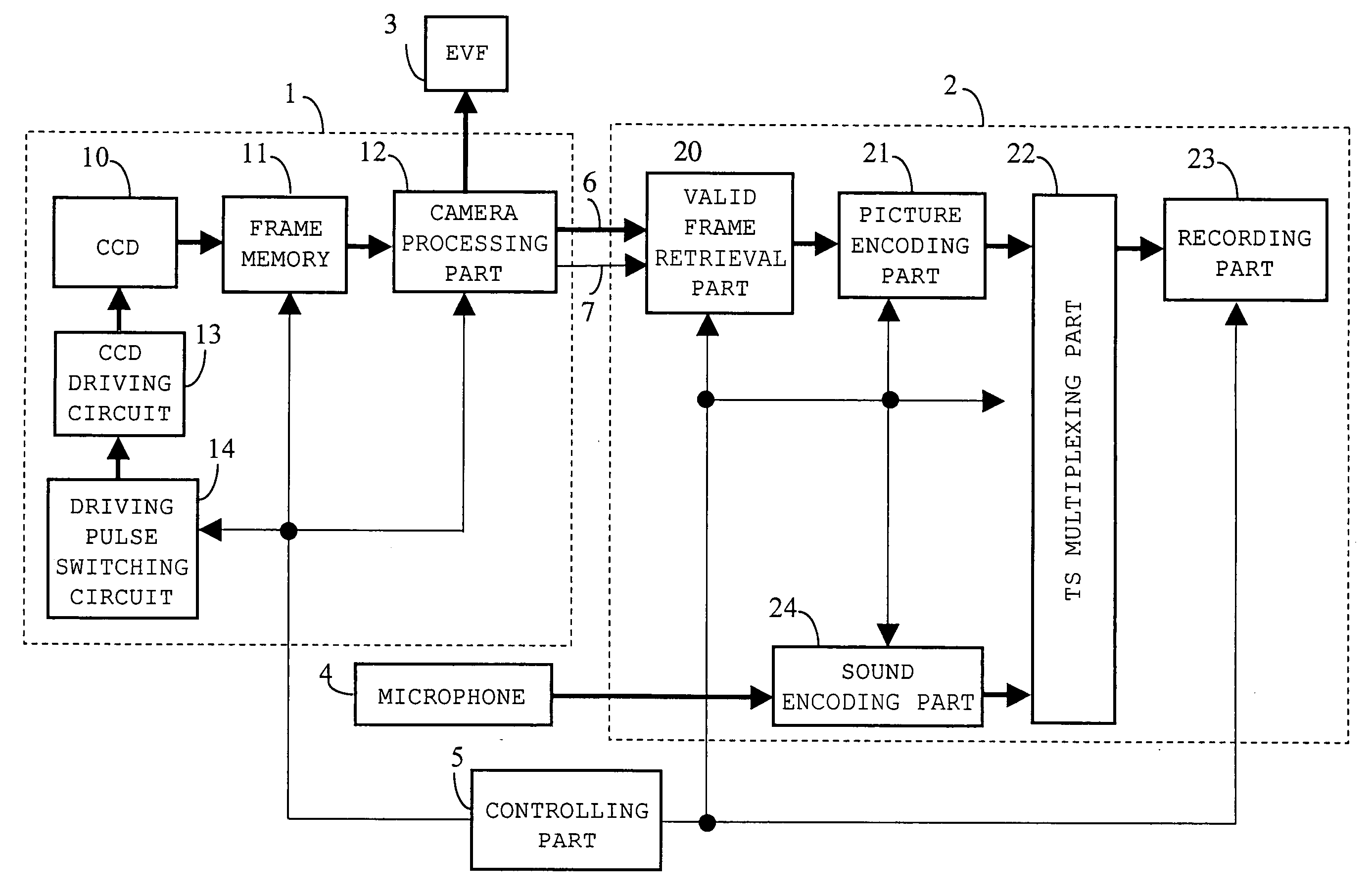
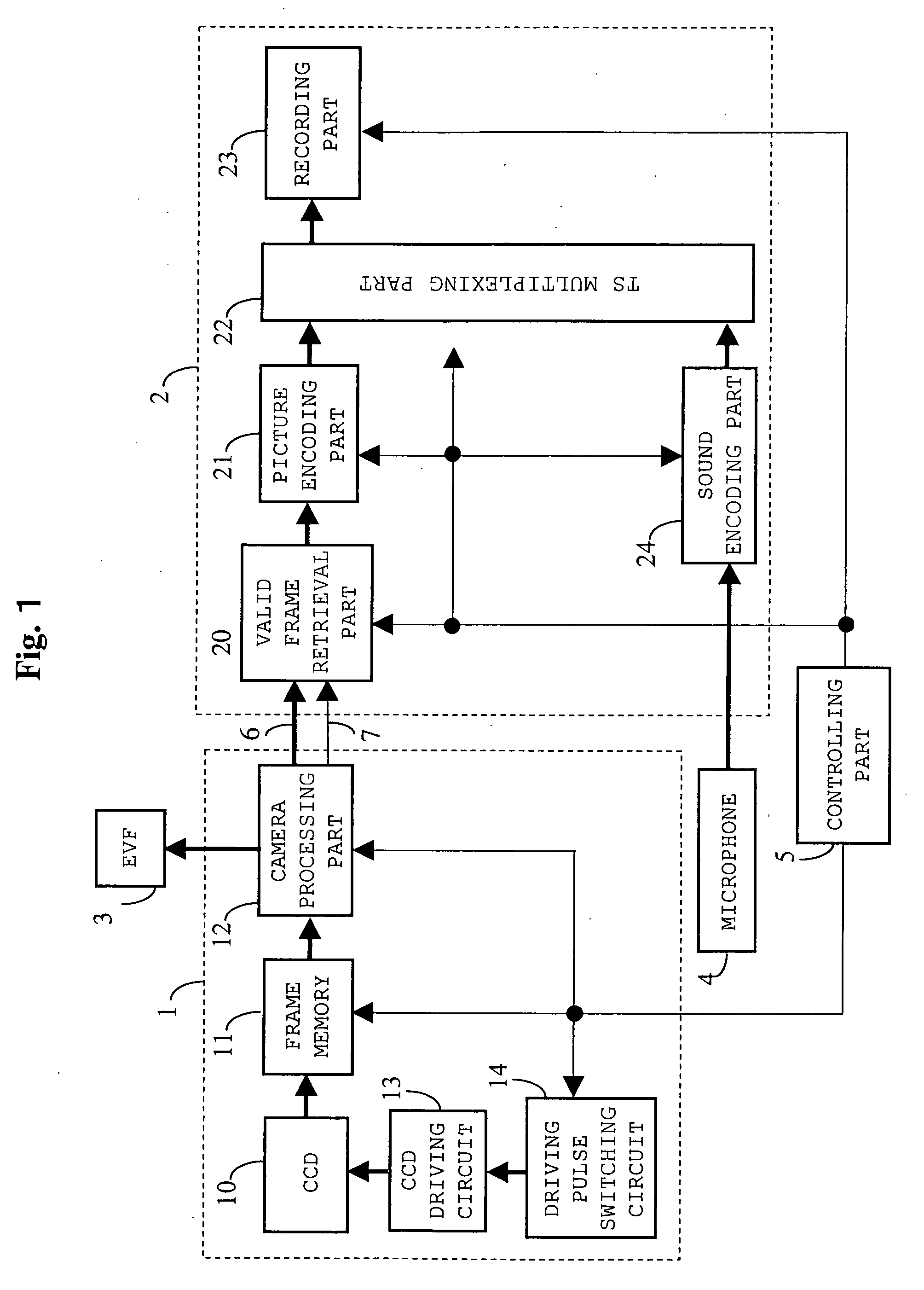
[0131]FIG. 1 is a block diagram illustrating an imaging / recording device with a video recording apparatus of embodiment 1 according to the present invention.

[0132] In FIG. 1; reference numeral 1 denotes an imaging device, 2 denotes a video recording apparatus, 3 denotes an electronic view finder (hereinafter abbreviated for EVF), 4 denotes a microphone, 5 denotes a controlling part, 6 denotes 60p picture signals, 7 denotes a valid frame flag for retrieving a valid frame corresponding to Xp picture signals output from CCD 10 from 60p picture signals.

[0133] Reference numeral 10 denotes a CCD, which can scan progressively, 11 denotes frame memory, 12 denotes a camera processing part for performing a camera process, 13 denotes a CCD driving circuit, and 14 denotes a driving pulse switching circuit for switching to and outputting a driving pulse corresponding to a multi-frame rate.

[0134] Reference numeral 20 denotes a valid frame retrieval part for retrieving a valid frame from 60p pi...

embodiment 2

[0179]FIG. 10 is a block diagram illustrating video recording apparatus 2 in embodiment 2 according to the present invention. The same numerals are given to the same components as those in FIGS. 1 and 3, and the detailed descriptions thereof are omitted. Reference numeral 90 denotes ATS value generation means, 91 denotes ATS multiplexing means, and 92 denotes a recording media controlling part.

[0180] If an actual available transfer rate is high when MPEG2-TS is transferred from TS multiplexing means 22 to recording means 23, a TS packet will be transferred intermittently. In order to record MPEG2-TS efficiently on a recording medium, unnecessary information such as Null packet in an actual transport stream may be removed. In this case, timing for a TS packet to be input and output to and from recording means 23 needs to be somehow recorded on a recording medium. Bru-ray disk or the like uses Arrival Time Stamp (ATS) for this purpose.

[0181] Effects of ATS on general recording and p...


PUM


Abstract

A video recording apparatus provides a slow motion effect or a quick motion effect by digitally converting the frame-rate instead of by changing the playback speed of the film, and using few recording media without requiring any special device at playing. A picture encoding part encodes only valid frames by changing a rate-controlling method so that a predetermined playing frame-rate is obtained at a standard data-rate at playing. And a TS multiplexing part multiplexes by converting a frequency of a standard STC clock by only a ratio of valid frame-rate and playing frame-rate, and generating values for PCR, PTS, and DTS.

Description

BACKGROUND OF THE INVENTION [0001] 1. Field of the Invention [0002] The present invention relates to a video recording apparatus such as a video camera, and more specifically to a video recording apparatus suitable for providing a slow motion effect or a quick motion effect in a movie by digitally, instead of using a film, converting the frame-rate, and a multiplexing method, a picture encoding method, a program, and a recording medium used for configuring the video recording apparatus. [0003] 2. Related Art of the Invention [0004] Conventionally, movies have been taken and edited with a film. Conventional film based video recording apparatus provides a slow motion effect or a quick motion effect in a movie by changing a recording frame-rate with fast forwarding or slow playing of the film. [0005] The advance of semiconductor technology, computer technology, and high-density recording technology has boosted picture quality and performance of a broadcasting apparatus system. Now, mor...

Claims


Application Information

Patent Timeline
Patent Type & Authority Applications(United States)
IPC IPC(8): H04N5/77H04N5/765H04N5/781H04N5/783H04N5/91H04N5/92H04N9/804H04N9/806
CPCH04N5/772H04N5/783H04N21/2387H04N9/8063H04N9/8042
Inventor SHIMAZAKI, HIROAKIMITA, HIDEAKISAITO, HIROSHI
Owner PANASONIC CORP
Learn More