Method for simulating optical components for the stereoscopic production of spatial impressions

a technology of optical components and spatial impressions, applied in the field of simulating spatial impressions, can solve the problems of high cost, laborious and expensive, and inconvenient teaching of this publication, and achieve the effect of reducing the cost of filter design, and reducing the cost of image processing

Inactive Publication Date: 2005-10-20
PHOENIX 3D +1
View PDF6 Cites 12 Cited by
  • Summary
  • Abstract
  • Description
  • Claims
  • Application Information

AI Technical Summary

Benefits of technology

[0020] Advantageously, the views Ak of the test scene are recorded by virtual or real cameras, the optical axes of the virtual or real cameras being aligned in parallel or converging, and the camera positions of any two neighboring views Ak preferably always have approximately the same distance. This feature can easily be implemented: Virtual cameras, which may be constituted, say, by a software-controlled PC, are arranged at equal distances on a circular arc, so that they converge in a certain point, called the fixed point. By contrast, the equidistant arrangement of virtual cameras on a straight line permits their being aligned in parallel.
[0098] The means a) through f) are preferably designed as a single unit, namely, a software-controlled PC. Means eligible as means g) are preferably a stereoscope or shutter glasses, and a monitor. It is also feasible, however, to utilize purely visual fusion without any aids for stereoscopic visualization. In this way, distortions of the results due to imperfections of the means used for stereoscopic visualization are avoided.

Problems solved by technology

The teaching of this publication, however, is not suitable either for simulating 3D impressions of arrangements with filter arrays.
While very good spatial impressions can be achieved with that method, the design of new filter arrays in combination with changing the respective image combination rules is a laborious and expensive affair.
So far, every new filter structure desired for trying its effect has to be fabricated as a material object, which makes filter design expensive.

Method used


Image

  • Method for simulating optical components for the stereoscopic production of spatial impressions
  • Method for simulating optical components for the stereoscopic production of spatial impressions
  • Method for simulating optical components for the stereoscopic production of spatial impressions

Examples


Embodiment Construction

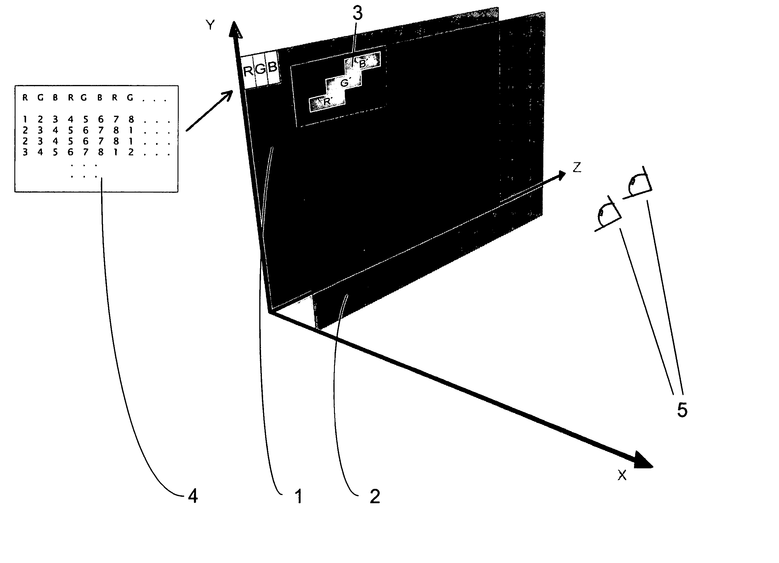
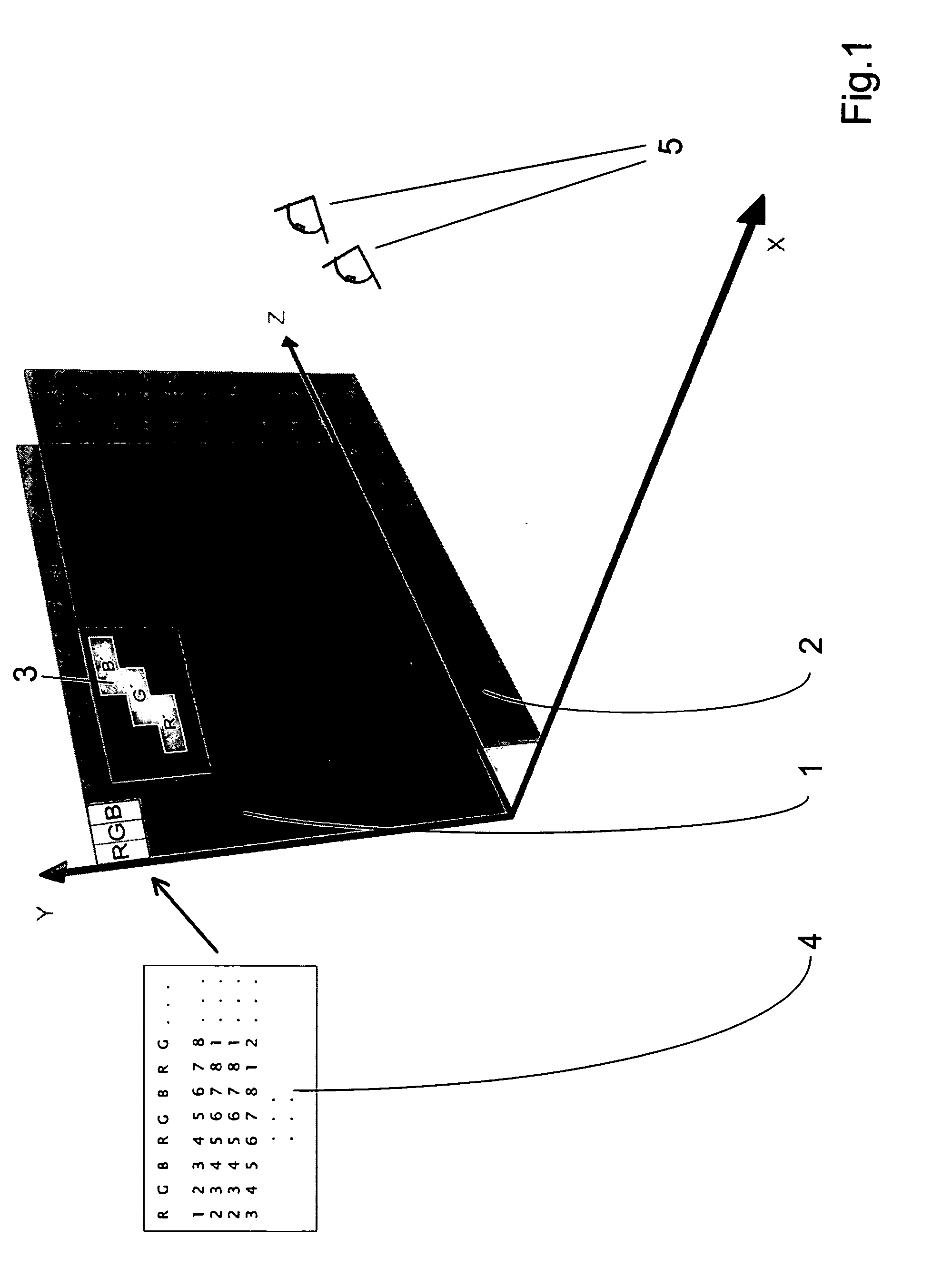
[0006] Proceeding from the prior art described, it is the purpose of the present invention to identify a method by which the spatial impressions to be produced by means of an image generator and a filter array can be simulated. The simulation method should be implementable by the simples and most cost-effective means. Further, it is the purpose of the invention to describe an arrangement for implementing the method.

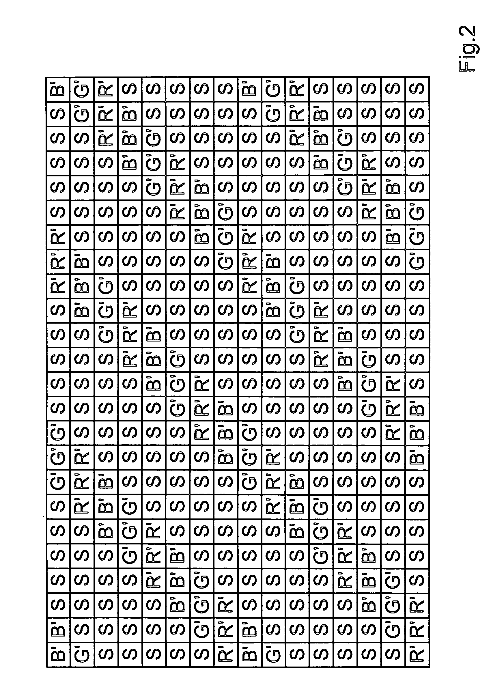
[0007] According to the invention, the problem is solved by a method for the simulation of spatial visual impressions, comprising the following steps: [0008] a) Specification of the geometry of an image generator, especially with regard to the structure and size of its image elements, [0009] b) specification of the geometry of a filter array, especially with regard to the structure and size of its filter elements, [0010] c) specification of a spatial arrangement geometry with regard to the image generator and the filter array in a three-dimensional coordinate system (X,Y...


PUM


Abstract

The invention relates to a simulation method, especially to a method for simulating spatial impressions which are produced by means of an image generator and one or several filter arrays. The method according to the invention essentially comprises the following steps: a) Specification of the geometry of the image generator, b) specification of the geometry of the filter array, c) specification of a spatial arrangement geometry in relation to the image generator and the filter array in a three-dimensional coordinate system (X,Y,Z), d) specification of two monocular positions of observation in front of the said arrangement geometry, e) specification of a combined image containing bits of partial information from several views Ak (k=1 . . . n) of a scene, f) determination of a first and a second secondary image containing image elements of the specified combined image which are visible to the eye of an observer in the specified first and second monocular position of observation on the basis of the specified filter array geometry in conjunction with the specified image generator geometry and the spatial arrangement geometry, and g) stereoscopic visualization of the first and second secondary images as a left and right stereoscopic image, respectively.

Description

FIELD OF THE INVENTION [0001] The invention relates to a simulation method, especially to a method for simulating spatial impressions which are produced by means of an image generator and one or several filter arrays. DESCRIPTION OF PRIOR ART [0002] U.S. Pat. No. 5,311,356 describes the simulation of the effects of optical lenses. For that purpose, sceneries are imaged on films by means of certain lenses. These films are offered to an observer's view for comparison. The film that gives the best visual impression indicates the lens to be selected. The method described in this publication, though, makes it possible only to record real scenes and to assess the resulting films in order to select a particular lens. The simulation of a 3D impression for filter arrays cannot be achieved by the teaching of the publication cited. [0003] Through WO 93 / 10475, a 3D arrangement using left and right stereo images is known, in which 3D objects / scenes are simulated by producing left and right parti...

Claims


Application Information

Patent Timeline
Patent Type & Authority Applications(United States)
IPC IPC(8): G02B27/22G06T19/00H04N13/00
CPCH04N13/0275G02B27/2228H04N13/275G02B30/34
Inventor TZSCHOPPE, WOLFGANG
Owner PHOENIX 3D
Why Eureka
Try Eureka