Saddle-contoured cap for a dermal tissue lancing device

Inactive Publication Date: 2005-10-20
LIFESCAN INC
View PDF16 Cites 83 Cited by
  • Summary
  • Abstract
  • Description
  • Claims
  • Application Information

AI Technical Summary

Benefits of technology

[0011] The continuous saddle-contoured compression surface has a three-dimensional profile that provides for reliable and complete contact between the cap and the target site and, hence, uniform application of pressure on the target site. The continuous saddle-cont

Problems solved by technology

However, conventional caps may not serve to reliably produce an adequate volume of biological fluid sample due to insufficient contact between the cap and the target site and/or non-uniform applicatio

Method used


Image

  • Saddle-contoured cap for a dermal tissue lancing device
  • Saddle-contoured cap for a dermal tissue lancing device
  • Saddle-contoured cap for a dermal tissue lancing device

Examples


Embodiment Construction

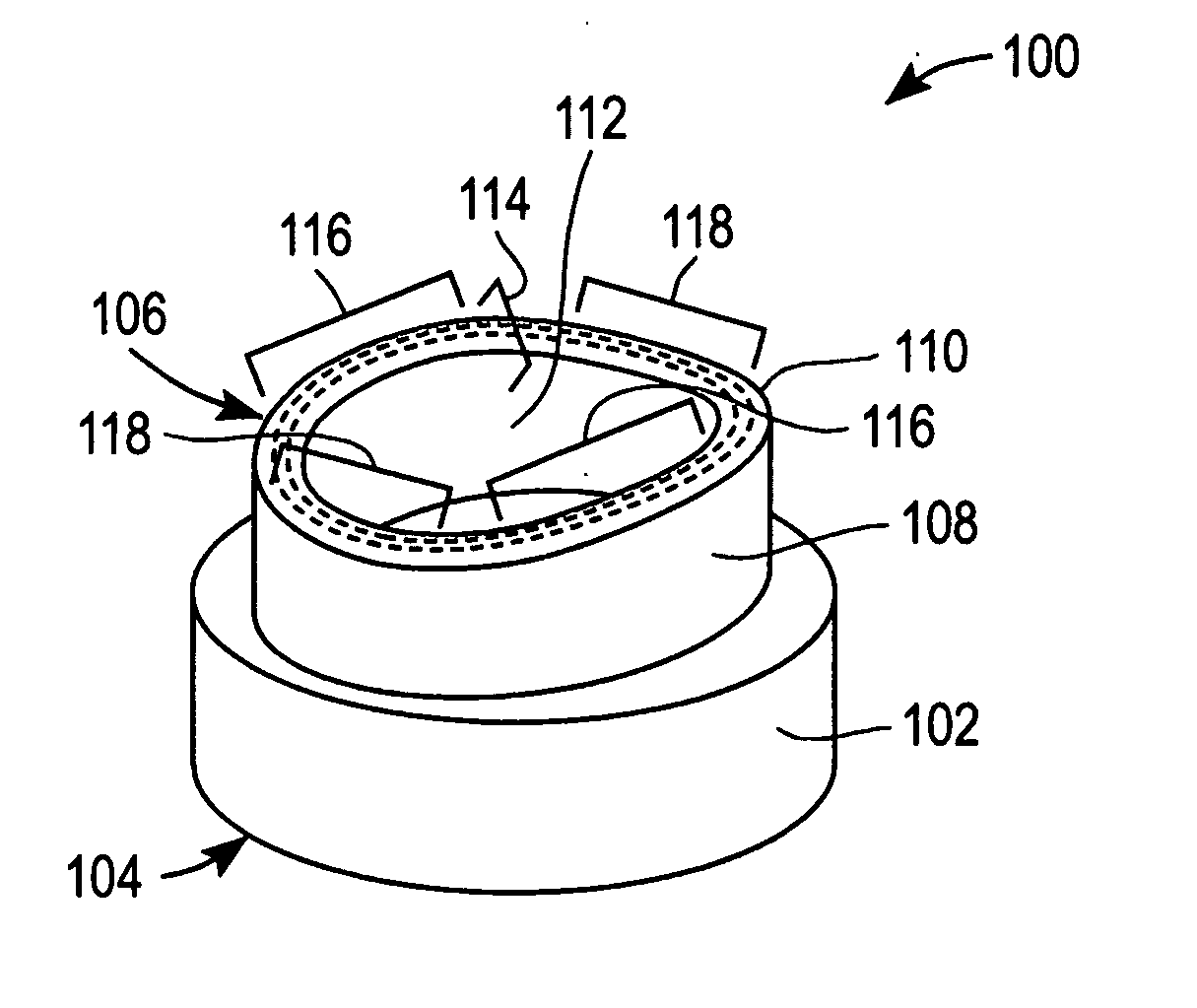
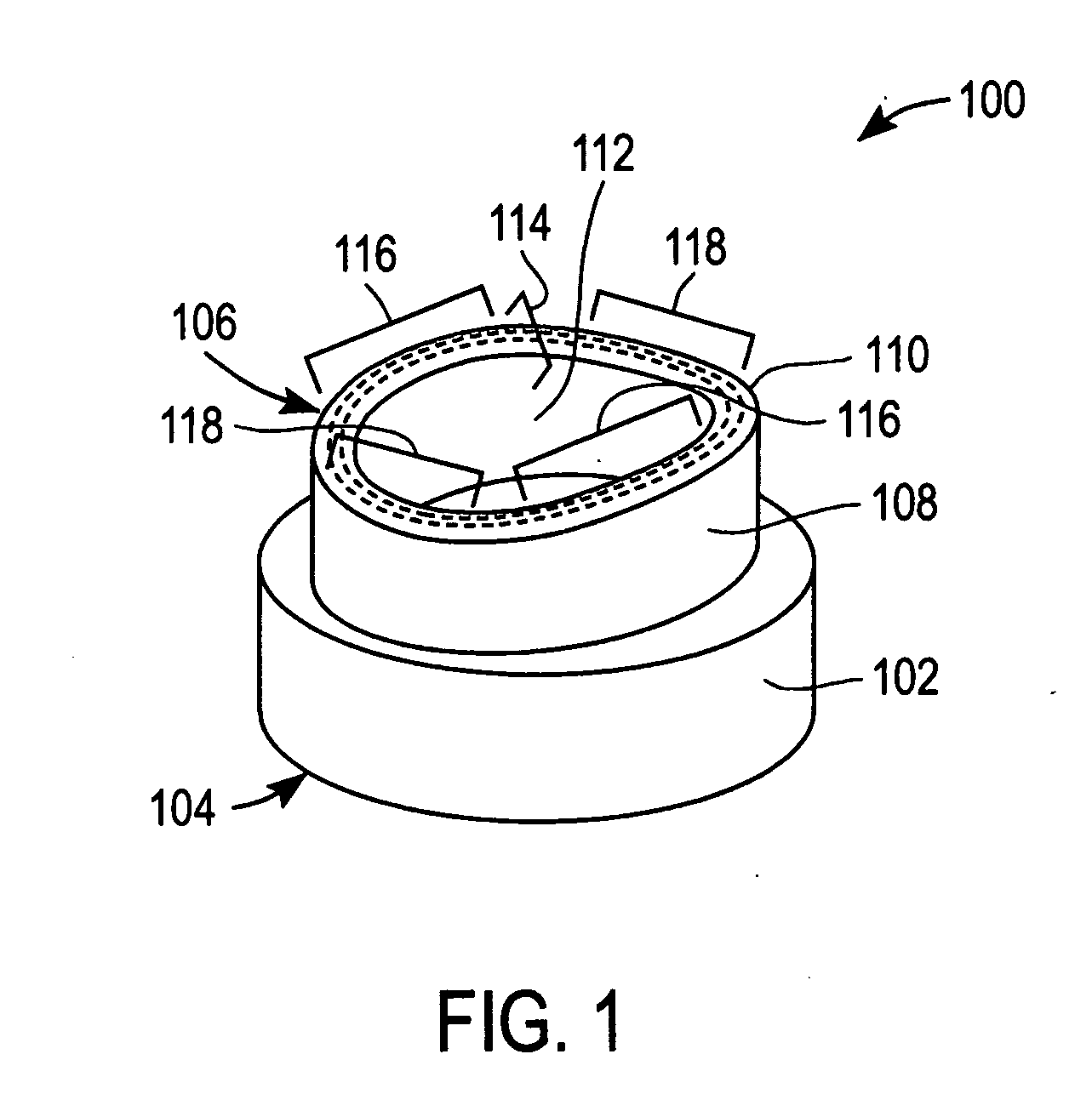
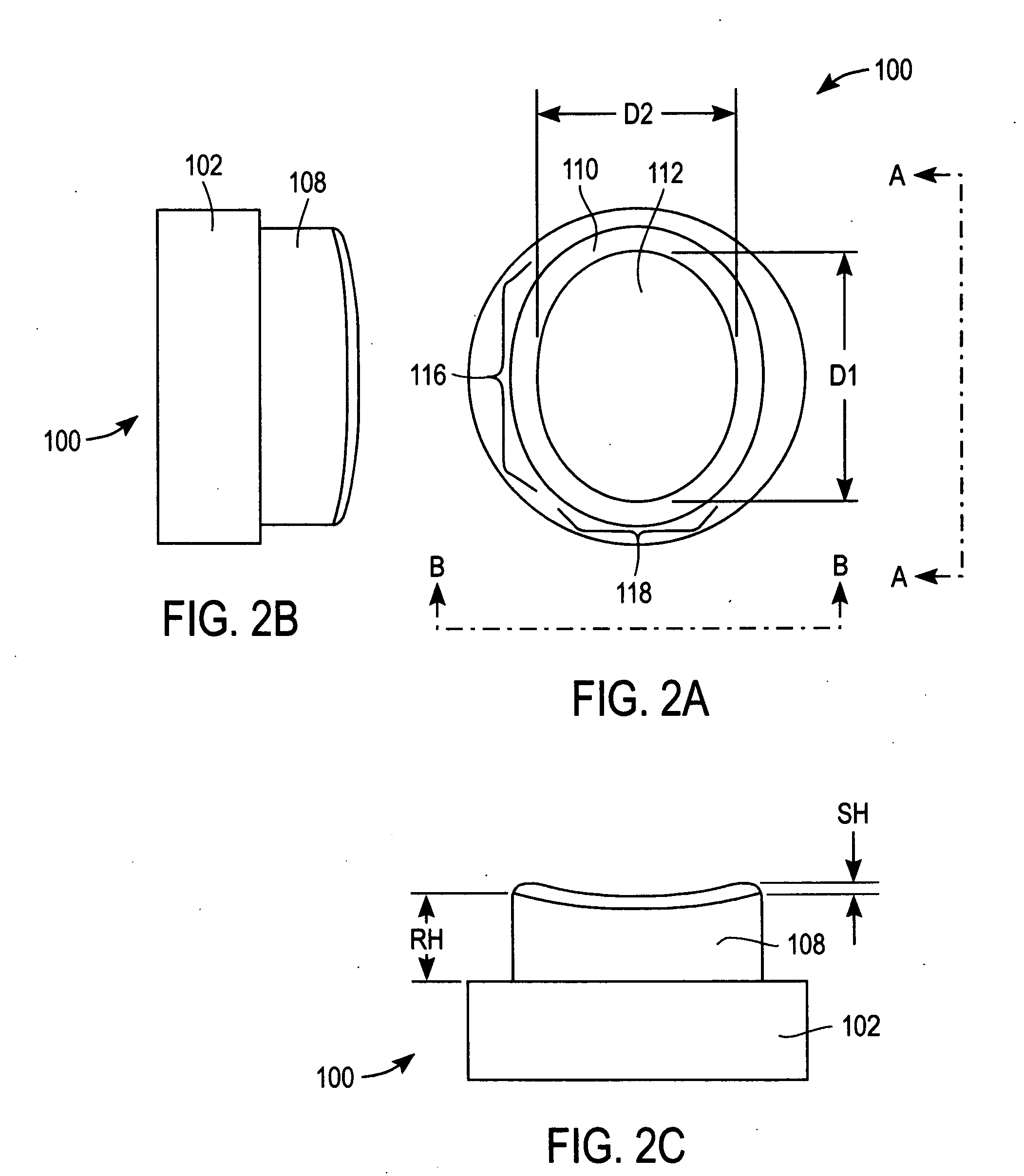
[0022]FIG. 1 is a simplified perspective view of a cap 100 for use with a dermal tissue lancing device (not shown) according to an exemplary embodiment of the present invention. Cap 100 includes a body 102 with a proximal end 104 and a distal end 106.

[0023] Cap 100 is configured to facilitate the flow of a biological fluid sample (e.g., a whole blood sample) out of a lanced dermal tissue target site with minimal or no manipulation (e.g., squeezing and / or milking) of the dermal tissue subsequent to lancing.

[0024] Proximal end 104 is configured to be removeably attached to an end of a dermal tissue lancing device (not shown) by, for example, slideably mounting, snap-fitting or screw-fitting proximal end 104 to the end of the dermal tissue lancing device. Alternatively, proximal end 104 of cap 100 can be configured for retention within a retainer (not shown) that is removeably attached to the end of a dermal tissue lancing device.

[0025] Once apprised of the present disclosure, one s...


PUM


Abstract

A cap for a dermal tissue lancing device that has a housing and a lancet moveable with respect to the housing includes a body with an opening therethrough for at least a portion of the lancet to pass through. The body of the cap has a proximal end configured for engagement with the housing and a distal end. Moreover, the distal end has a projection and a rim with a continuous saddle-contoured compression surface for engaging a dermal tissue target site. When the cap contacts and is urged towards the dermal tissue target site, the continuous saddle-contoured compression surface applies substantially uniform pressure against the dermal tissue target site.

Description

CROSS-REFERENCE [0001] This application is a continuation-in-part application of U.S. application Ser. No. 10 / 825,899, filed Apr. 16, 2004, which is incorporated herein by reference in its entirety and to which application we claim priority under 35 USC §120.BACKGROUND OF THE INVENTION [0002] 1. Field of the Invention [0003] The present invention relates, in general, to medical devices and, in particular, to lancing devices. [0004] 2. Description of the Related Art [0005] Conventional lancing devices generally have a rigid housing and a lancet that can be armed and launched so as to protrude from one end of the lancing device. For example, conventional lancing devices can include a lancet that is mounted within a rigid housing such that the lancet is movable relative to the rigid housing along a longitudinal axis thereof. Typically, the lancet is spring loaded and launched, upon release of the spring, to penetrate (i.e., “lance”) a target site (e.g., a dermal tissue target site). A ...

Claims


Application Information

Patent Timeline
IPC IPC(8): A61B5/151A61B5/15A61B17/14A61B17/32A61L31/00
CPCA61B5/1411A61B5/150022A61B5/150068A61B5/150748A61B5/151A61B5/00A61B5/14A61B5/1405
Inventor ALLEN, JOHN
Owner LIFESCAN INC
Why Eureka
Try Eureka