Deceleration control apparatus and deceleration control method for vehicle

a control apparatus and vehicle technology, applied in the direction of brake systems, instruments, tractors, etc., can solve the problems of unnecessary control and unnecessary warnings

Inactive Publication Date: 2005-10-20
TOYOTA JIDOSHA KK
View PDF9 Cites 50 Cited by
  • Summary
  • Abstract
  • Description
  • Claims
  • Application Information

AI Technical Summary

Benefits of technology

[0009] It is an object of the invention to provide a deceleration control apparatus and deceleration control method for a vehicle, which makes it possible to apply desired deceleration to a vehicle so that a driver feels comfortable.
[0019] In the first aspect, the calculation device may correct the target deceleration such that a maximum lateral acceleration becomes smaller as a friction coefficient of a road becomes smaller.

Problems solved by technology

As a result, an unnecessary warning may be given, and unnecessary control may be performed.

Method used


Image

  • Deceleration control apparatus and deceleration control method for vehicle
  • Deceleration control apparatus and deceleration control method for vehicle
  • Deceleration control apparatus and deceleration control method for vehicle

Examples


first embodiment

[0039] A first embodiment will be described with reference to FIG. 1 to FIG. 11. The first embodiment relates to a deceleration control apparatus for a vehicle, which performs deceleration control using a brake (braking device).

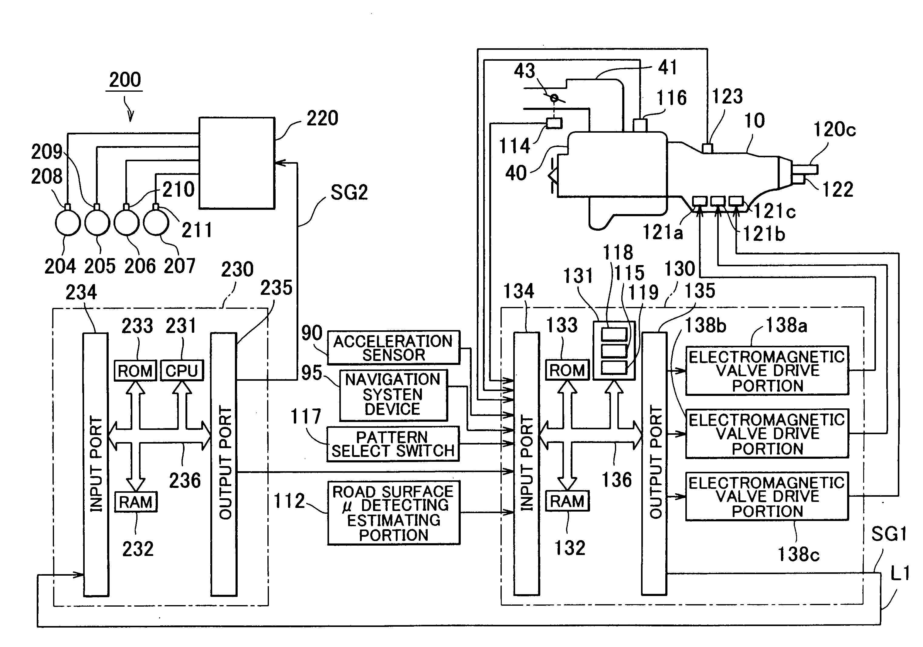
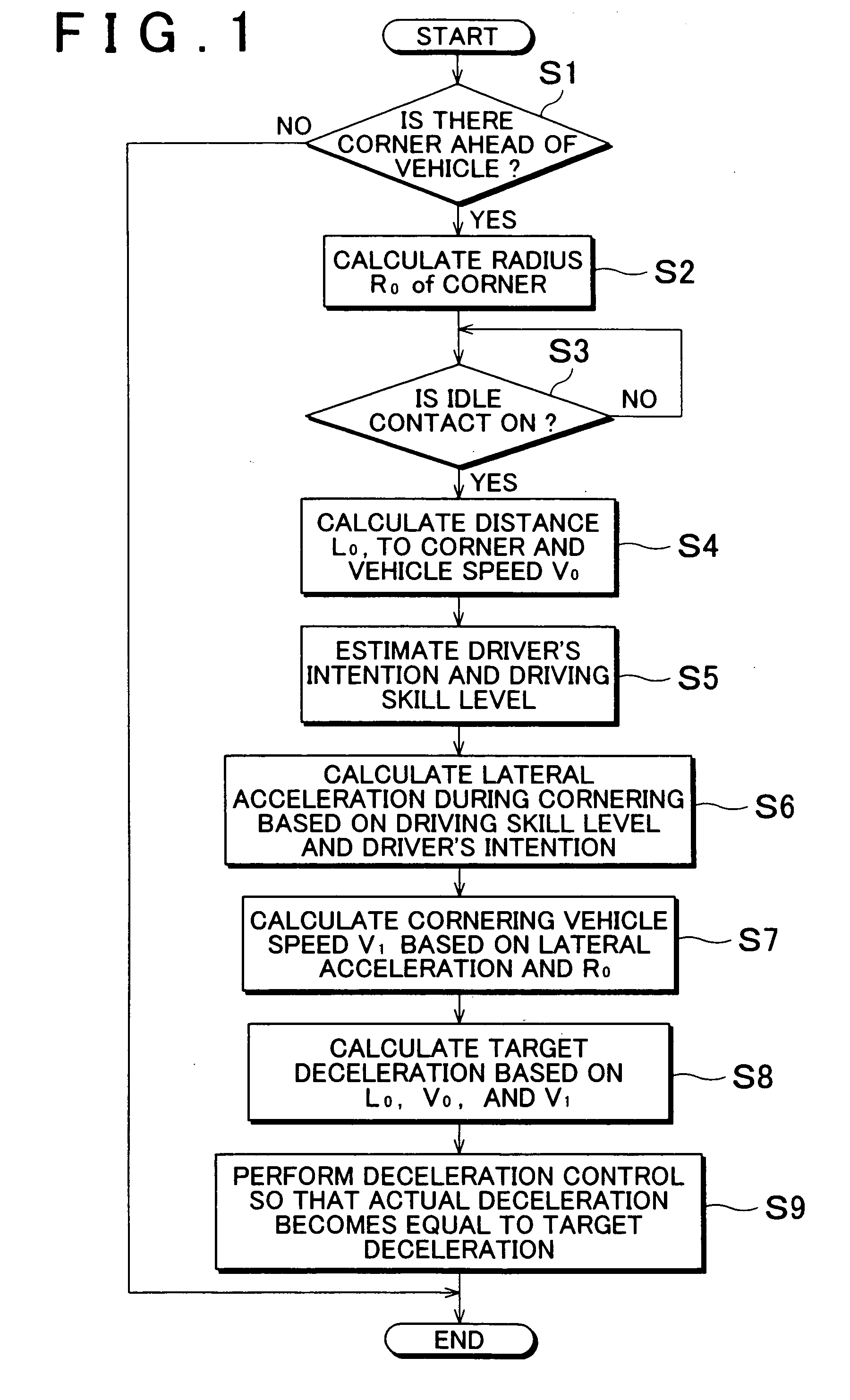
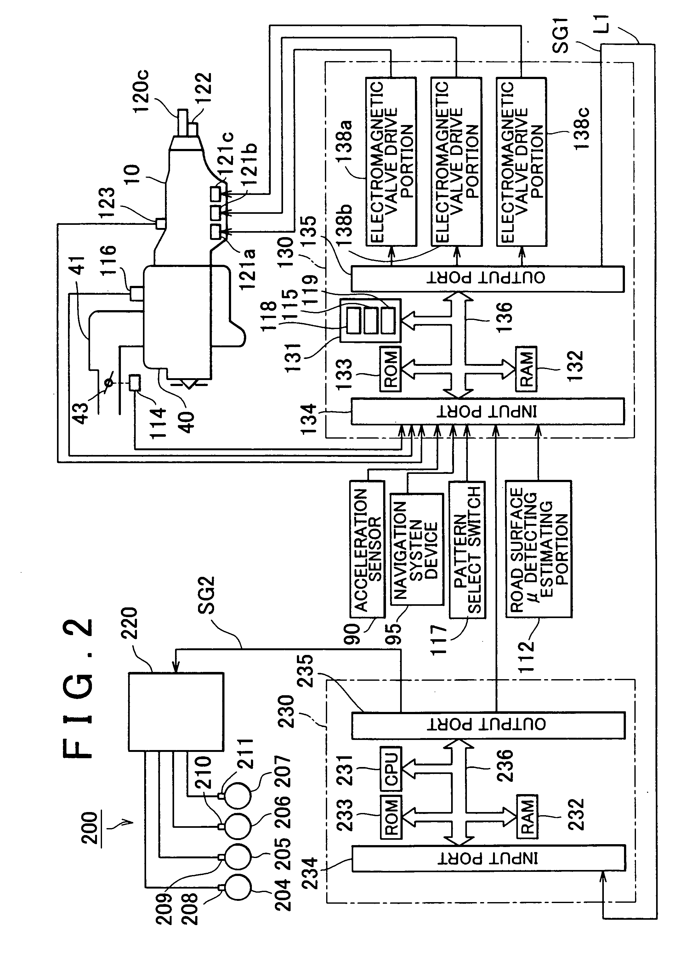
[0040] In this embodiment, in deceleration control which decreases a vehicle speed to an appropriate cornering vehicle speed when a corner is detected ahead of a vehicle, and driver's intention to perform deceleration is detected, a target gravitational deceleration (hereinafter, referred to as “target deceleration”) is calculated based on driver's intention relating to running of the vehicle, a driving skill level, a vehicle speed when an accelerator pedal is released, a distance to the corner, and a radius of the corner. The deceleration control is performed so that actual deceleration becomes equal to the target deceleration. Thus, the deceleration control which allows the driver to feel comfortable is performed.

[0041] As described later in detail, a dec...

second embodiment

[0146] Next, a second embodiment will be described. The second embodiment relates to a deceleration control apparatus which performs cooperative control of the brake (brake device) and the automatic transmission. In the second embodiment, description of the same portions as in the first embodiment will be omitted, and only characteristic portions will be described.

[0147] In the second embodiment, the same operations as those in steps S1 to S8 in FIG. 1 in the first embodiment are performed. An operation in step S9 in the second embodiment is different from the operation in step S9 in the first embodiment. That is, in the first embodiment, the deceleration control is performed so that the deceleration applied to the vehicle becomes equal to the target deceleration obtained in the aforementioned step S8, using only the brake. Meanwhile, in the second embodiment, deceleration control is performed so that the deceleration applied to the vehicle becomes equal to the target deceleration ...

third embodiment

[0171] Next, a third embodiment will be described.

[0172] Description of the same portions as in the aforementioned embodiments will be omitted, and only the characteristic portion will be described.

[0173] In the third embodiment, the target deceleration calculated in the aforementioned step S8 in FIG. 1 is corrected by a road inclination in step S9, whereby deceleration at which the driver feels more comfortable can be obtained (i.e., deceleration expected by the driver can be obtained). That is, in the third embodiment, an operation in step S9 is different from the operation in step S9 in the first embodiment or the second embodiment (operations in steps S1 to S8 are the same as in the first embodiment or the second embodiment).

[0174] [Step S9]

[0175] In step S9 in the third embodiment, the road inclination measuring estimating portion 118 measures or estimates the road inclination. Next, an inclination correction amount (deceleration) corresponding to the road inclination measur...


PUM


Abstract

A target deceleration for running on a curved road ahead of a vehicle is obtained, based on a driver's intention which is input or estimated, and a driver's driving skill level which is input or estimated; and deceleration control is performed so that deceleration applied to the vehicle becomes equal to the target deceleration. In a case where the driver's intention is to cause the vehicle to respond to driving operation relatively quickly, the target deceleration may be set to a relatively small value; and in a case where the driving skill level is relatively high, the target deceleration is set to a relatively small value. Further, the target deceleration is decided based on a state of a road where the vehicle runs.

Description

INCORPORATION BY REFERENCE [0001] The disclosure of Japanese Patent Application No. 2004-119238 filed on Apr. 14, 2004 including the specification, drawings and abstract is incorporated herein by reference in its entirety. BACKGROUND OF THE INVENTION [0002] 1. Field of the Invention [0003] The invention relates to a deceleration control apparatus and deceleration control method for a vehicle. More particularly, the invention relates to a deceleration control apparatus and deceleration control method for a vehicle, which performs deceleration control that allows a driver to feel comfortable. [0004] 2. Description of the Related Art [0005] Japanese Patent Application Publication No. JP-A-2003-99897 discloses a technology in which only a warning is given during cornering in a case where a highly skilled driver drives a vehicle, and a warning is given and deceleration control is performed during cornering in a case where a less skilled driver drives a vehicle, that is, a technology in w...

Claims


Application Information

Patent Timeline
Patent Type & Authority Applications(United States)
IPC IPC(8): B60W10/04B60K28/00B60T7/12B60T8/00B60T8/32B60W10/00B60W10/06B60W10/10B60W10/18B60W10/188B62D37/00F02D29/00F02D29/02F16H59/48F16H59/66F16H61/02F16H61/21G06F17/00
CPCB60W10/06B60W2720/125B60W10/18B60W40/068B60W40/072B60W40/076B60W40/09B60W50/10B60W2540/22B60W2550/14B60W2550/143B60W2550/148B60W2550/402B60W2720/106B60W10/10B60W2540/221B60W2552/00B60W2552/20B60W2552/30B60W2552/40B60W2556/50
Inventor SHIIBA, KAZUYUKIIWATSUKI, KUNIHIROIIZUKA, SHINYA
Owner TOYOTA JIDOSHA KK
Why Eureka
Try Eureka