Mounting bracket, rolling bearing and corresponding assembly method

Inactive Publication Date: 2005-10-27
AB SKF
View PDF11 Cites 23 Cited by
  • Summary
  • Abstract
  • Description
  • Claims
  • Application Information

AI Technical Summary

Benefits of technology

[0008] Described herein is a mounting bracket allowing secure and reliable mounting on an

Problems solved by technology

Too much radial interference results in considerable assembly effort, leading to the risk of the tongues breaking during the assembly.
Too little radial interference makes it easier to assemble the bracket on the race but entails the risk of poor mounting of said bracket and of uncoupling between the bracke

Method used


Image

  • Mounting bracket, rolling bearing and corresponding assembly method
  • Mounting bracket, rolling bearing and corresponding assembly method
  • Mounting bracket, rolling bearing and corresponding assembly method

Examples


Embodiment Construction

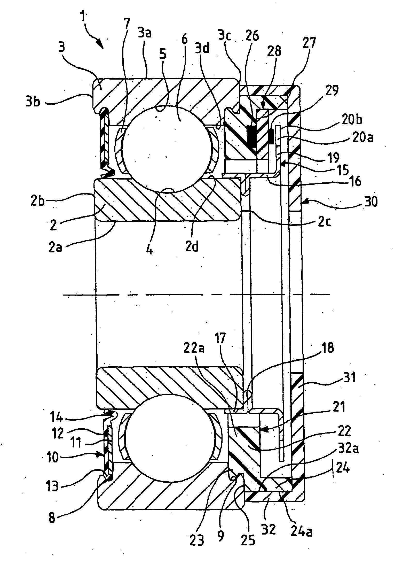
[0037] In FIG. 1, an instrumented rolling bearing, referenced 1 in its entirety, includes a rotating inner race 2 and a nonrotating outer race 3. The rotating race 2 is provided with a bore 2a, with lateral radial faces 2b, 2c, and with a toroidal raceway 4 formed on an outer cylindrical surface 2d. The nonrotating race 3 includes an outer cylindrical surface 3a, lateral radial faces 3b, 3c and a toroidal raceway 5 formed on an inner surface 3d. Rolling elements 6, in this case balls, are arranged between the raceways 4,5 of the rotating race 2 and nonrotating race 3. The rolling elements 6 are kept circumferentially spaced by a cage 7.

[0038] The nonrotating race 3 includes, on its inner surface 3d, a first annular groove 8 situated axially close to one lateral face 3b and a second annular groove 9 situated axially close to the other lateral face 3c and being symmetrical to the annular groove 8 with respect to a radial plane passing through the center of the rolling elements 6.

[00...


PUM


Abstract

A bracket includes a fixing piece on a rotation element (3), said fixing piece comprising a body (22) in the general form of a ring, provided with an annular radial projection (23). The body includes an opening (33) which permits a variation in the diameter of said body (22) on assembly with engagement of the projection (23) in a corresponding groove (9) on the rotation element (3) to give a radial interference fit. A bar (28) prevents a variation in the diameter of the body (22) as above after the assembly thereof.

Description

BACKGROUND OF THE INVENTION [0001] 1. Field of the Invention [0002] The subject of the present invention is a mounting bracket of the type used for mounting a sensor or encoder system on a race of an instrumented rolling bearing, and a corresponding assembly method. [0003] 2. Description of the Relevant Art [0004] An instrumented rolling bearing generally includes a rotating race, a nonrotating race, an encoder system mounted on the rotating race, and a sensor system mounted on the nonrotating race. The means for mounting the sensor or encoder system on a race must make it possible to prevent poor mounting that would lead to measuring errors or uncoupling between the sensor or encoder system and the corresponding race, rendering the instrumented rolling bearing unusable. [0005] Document FR 0 376 771 discloses a bracket for the sensor system of an instrumented rolling bearing including a drum cut at one end into a plurality of circumferentially spaced elastic tongues, each tongue bei...

Claims


Application Information

Patent Timeline
IPC IPC(8): F16C41/00G01P3/44
CPCG01P3/443F16C41/008F16C19/06F16C41/007F16C33/80F16C2300/02
Inventor NIARFEIX, FRANCOIS
Owner AB SKF
Why Eureka
Try Eureka