Precision hand-held wire stripper

a wire stripper and hand-held technology, applied in the field of hand-held wire strippers, can solve the problems of reducing the chances of nicking or damaging the wire during slug removal, and achieve the effects of high precision insulation cutting, avoiding nicking the metal conductor of the wire, and increasing precision

Active Publication Date: 2005-10-27
IDEAL IND INC
View PDF8 Cites 15 Cited by
  • Summary
  • Abstract
  • Description
  • Claims
  • Application Information

AI Technical Summary

Benefits of technology

[0003] The present invention is directed to a hand-held wire stripper having reciprocating cutting blades mounted on reciprocating jaws with the jaws and at least one of the blades being connected to handles for actuation. A primary object of the invention is a wire stripper of the type described which

Problems solved by technology

This further reduces the chances of nickin

Method used


Image

  • Precision hand-held wire stripper
  • Precision hand-held wire stripper
  • Precision hand-held wire stripper

Examples


Embodiment Construction

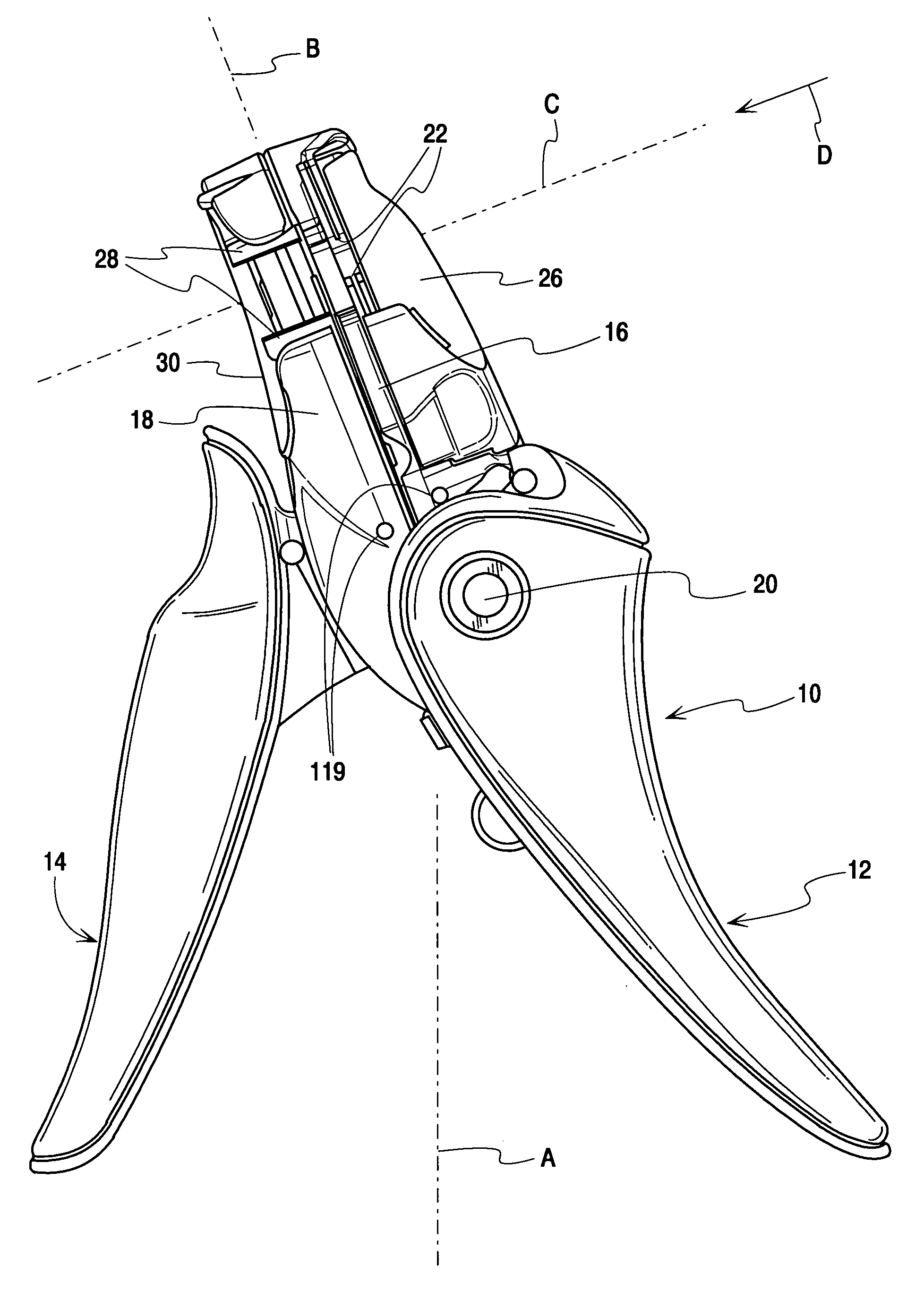
[0068]FIG. 1 illustrates the wire stripper 10 of the present invention. While the view of FIG. 1 is referred to herein as a front view of the wire stripper, it will be understood that this notation is somewhat arbitrary and is for reference purposes only. FIG. 1 is the view of the tool as it would normally be seen lying on a table but in a user's hand in the normal working position, the tool would be seen from the right side of FIG. 1. In the various views of this specification the front, side, rear and plan views of a part are referenced as the part would be oriented in the view of FIG. 1.

[0069] The major components of the wire stripper 10 include a blade handle 12, a gripper handle 14, a blade jaw 16 and a gripper jaw 18. All four of these components are pivotally connected to one another at a common pivot pin 20. A set of cutting blades 22 is mounted on the blade jaw 16 in a manner which will be described below. The blades are actuated by a link connected between one of the blad...


PUM


Abstract

A wire stripper has a blade handle, a gripper handle, a blade jaw and a gripper jaw all pivotally connected at a main pivot pin that is offset from the mating faces of the jaws. Movable and floating cutting blades mounted on the blade jaw are self-aligning due to a floating connection of the blades that allows them to move respective gauge surfaces into engagement during closing. A blade hold down spring urges the blades into alignment. The jaws are angled with respect to the handle axis so the throat of the cutting blades aligns with a user's line of sight. Individual handle springs have differential springs rates and are arranged so that the handles springs do no resist opening of the jaws.

Description

BACKGROUND OF THE INVENTION [0001] This invention is a hand-held wire stripper. In particular, the invention concerns a wire stripper which has a set of reciprocating jaws on which are mounted reciprocating wire stripper blades. Tools of this type provide an action in which the blades close on the end of a wire to cut its insulation and form an insulation slug to be pulled off the end of the wire. After the slug is cut the jaws separate in a direction generally parallel to the wire to pull the insulation slug off the conductor. This is followed by the blades opening to release the wire and by the jaws reclosing to prepare for the next cycle of operation. Typically wire strippers of this type also have a set of reciprocating grippers mounted on the jaws and which move generally in tandem with the blades to close on the unstripped portion of the wire and hold it fixed while the slug is pulled off. An example of a wire stripper of this type is shown in U.S. Pat. No. 2,523,936, the disc...

Claims


Application Information

Patent Timeline
IPC IPC(8): H02G1/12
CPCH02G1/1212
Inventor MURPHY, STACEY A.EATON, EDWARD T.
Owner IDEAL IND INC
Why Eureka
Try Eureka