Musical performance apparatus

Inactive Publication Date: 2005-10-27
YAMAHA CORP
View PDF3 Cites 12 Cited by
  • Summary
  • Abstract
  • Description
  • Claims
  • Application Information

AI Technical Summary

Benefits of technology

[0016] In a second aspect of the invention, both of the serial clock signal and word sync signal used in the aforementioned musical performance apparatus are produced using a single clock generator. This reduces the number of clock generators, which in turn simplifies the constitution of the performance control

Problems solved by technology

However, the aforementioned musical performance apparatus has the limited number of operators that can be simultaneously controlled; hence, it has difficulty in coping with simultaneous generation of numerous musical tones due to recent developments of technologies regarding electronic musical instruments.
Such a problem may apparently occur as the number of

Method used


Image

  • Musical performance apparatus
  • Musical performance apparatus
  • Musical performance apparatus

Examples


first embodiment

1. First Embodiment

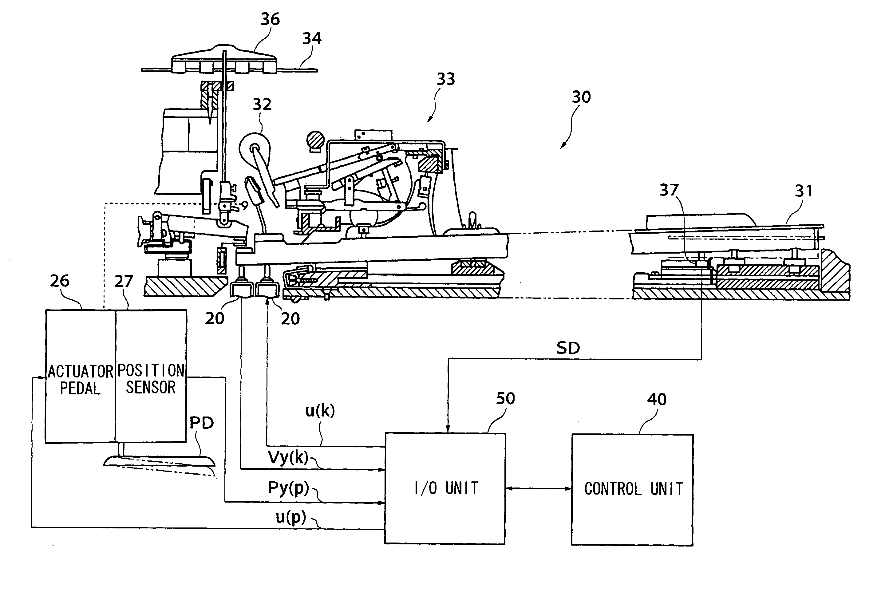
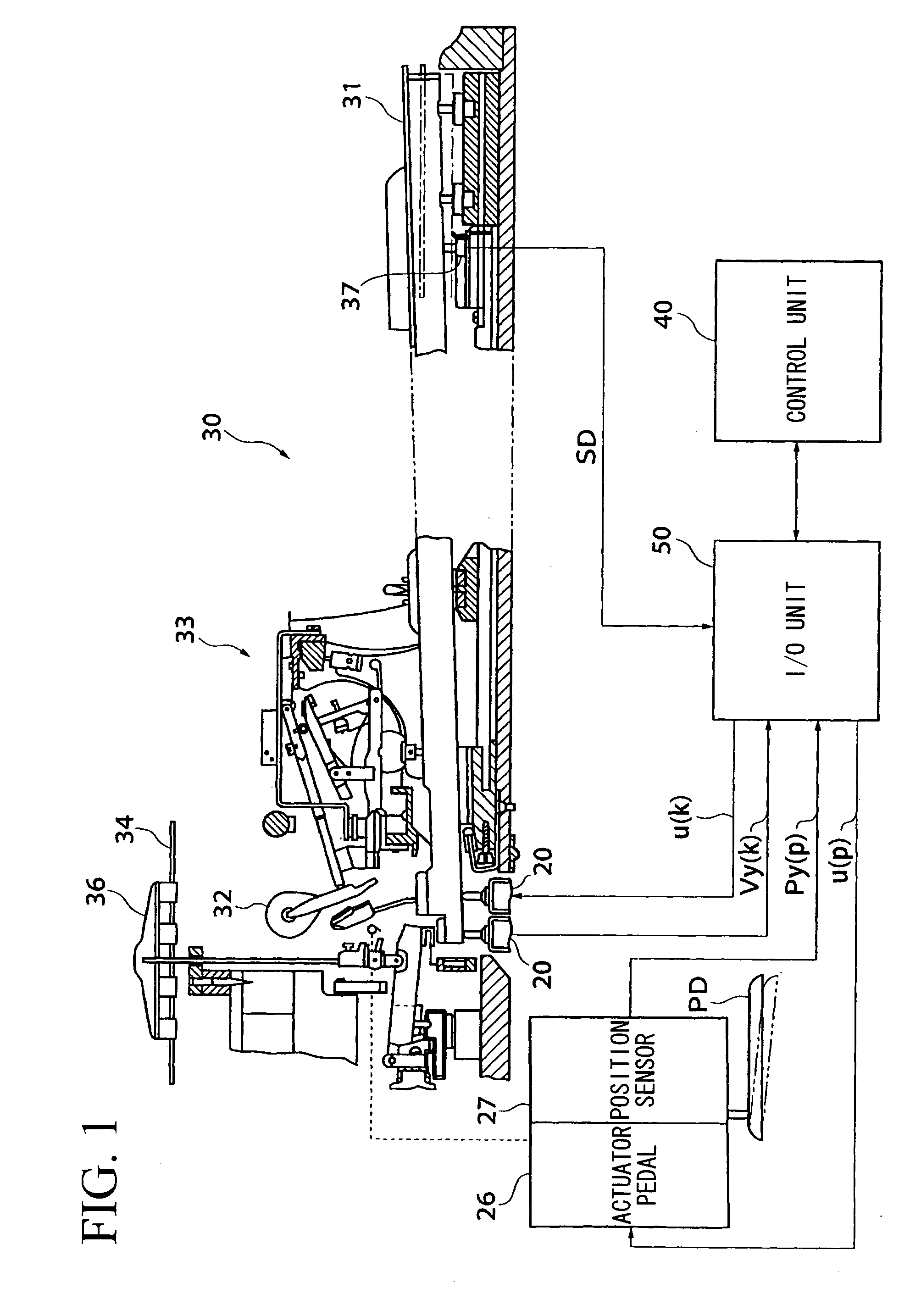
[0035]FIG. 1 is a fragmentary cross-sectional view showing the mechanism of a musical performance apparatus (such as a player piano, referred to as a keyboard musical instrument) equipped with electronic controls with respect to each single key. A keyboard assembly 30 has the mechanism similar to that adapted to conventionally-known acoustic pianos, wherein it includes an action mechanism 33 for transmitting the motion of a key 31 to a hammer 32, a string (or strings) 34 that is struck by the hammer 32, and a damper 36 for suspending vibration of the string 34 with respect to each single key 31. For the sake of convenience, the player's side close to the key 31 will be referred to as a front side.

[0036] A key drive unit 20 having a solenoid coil (not shown) is arranged beneath the rear end portion of the key 31. A key sensor unit 37 is arranged beneath the front side of the key 31, wherein it produces a detection signal SD (i.e., an analog signal) representing th...

second embodiment

2. Second Embodiment

[0072] The second embodiment is basically similar to the first embodiment as shown in FIGS. 1, 3, 5A-5F, and 6A-6D; hence, the detailed description thereof will be omitted as necessary.

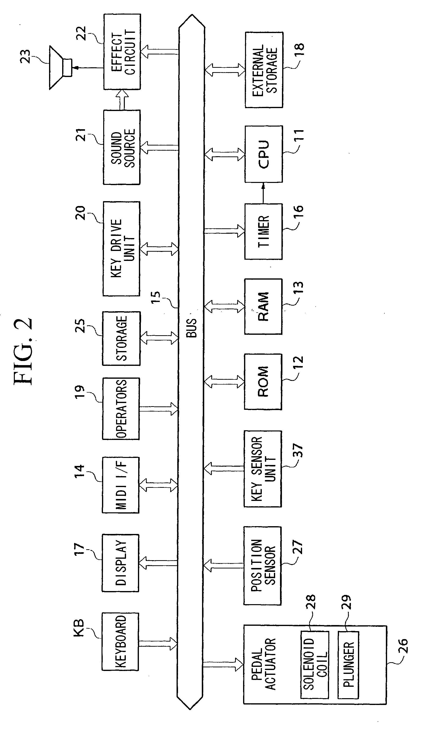
[0073]FIG. 7 is a block diagram showing the control mechanism of the keyboard assembly 30, wherein compared with the aforementioned block diagram shown in FIG. 2, the key drive unit 20 includes a solenoid 38 and a plunger 39. In addition, connection lines in the I / O unit 50 are configured by three-line buses such as I2S buses allowing transmission of digital musical tone signals.

[0074]FIG. 8 is a circuit diagram showing the internal configuration of each ASIC included in the I / O unit 50, wherein the DSP 51 supplies each ASIC 52 with a serial clock signal SCK and a word sync signal WS, which are supplied to A / D converters 53, shift registers 54, and latch circuits 55 respectively.

[0075] A single trailing edge of the word sync signal WS occurs at each time when trailing edges of t...


PUM


Abstract

A musical performance apparatus has an I/O unit including a digital signal processor (DSP) and a plurality of application-specific integrated circuits (ASIC), which are connected together in a cascade connection manner and each of which includes a plurality of shift registers. The DSP produces drive signals for driving a plurality of operators (e.g., keys and pedals) based on performance data. In synchronization with a serial clock signal, drive signals are transferred in a serial manner from the DSP to the shift registers. In synchronization with a word sync signal based on the serial clock signal, detection signals representing displacements of the operators are transferred in parallel to the shift registers, which in turn output drive signals in parallel. Both of the serial clock signal and word sync signal are produced using a single clock generator.

Description

BACKGROUND OF THE INVENTION [0001] 1. Field of the Invention [0002] This invention relates to musical performance apparatuses such as player pianos that perform feedback controls individually with respect to operators such as pedals and keys in accordance with performance information. [0003] This application claims priorities on Japanese Patent Applications Nos. 2004-127143 and 2004-205039, the contents of which are incorporated herein by reference. [0004] 2. Description of the Related Art [0005] Conventionally, various types of musical performance apparatuses such as player pianos have been developed and designed such that operators such as keys and pedals are individually driven by feedback controls based on displacements thereof in accordance with performance information, thus realizing automatic performance. [0006] Japanese Patent Application Publication No. H06-214560 discloses time-sharing servo controls with respect to a musical performance apparatus, wherein in the precondit...

Claims


Application Information

Patent Timeline
IPC IPC(8): A63H5/00G04B13/00G10F1/02G10H1/00G10H7/00
CPCG10F1/02
Inventor ISHII, JUNOBA, YASUHIKO
Owner YAMAHA CORP
Why Eureka
Try Eureka