Method and apparatus for mold component locking using active material elements

a technology of active materials and mold components, applied in auxillary shaping apparatus, manufacturing tools, food shaping, etc., can solve the problems of not being able to disclose actual measurement and then correct such shifting, and achieve the effect of reducing flash, reducing flash, and reducing flash

Inactive Publication Date: 2005-10-27
HUSKY INJECTION MOLDING SYST LTD
View PDF31 Cites 12 Cited by
  • Summary
  • Abstract
  • Description
  • Claims
  • Application Information

AI Technical Summary

Benefits of technology

[0010] It is an advantage of the present invention to provide injection molding machine apparatus and method to overcome the problems noted above, and to provide an effective, efficient means for urging a side core insert against the side wall of the mold core in an injection molding machine.
[0011] According to a first aspect of the present invention, structure and / or steps are provided for reducing flash in an injection mold which molds a molded article between a first mold surface and a second mold surface, including an active material actuator configured to, in response to application or removal of an electrical actuation signal thereto, change dimension and urge the first mold surface toward the second mold surface to reduce flash therebetween, and transmission structure configured to provide, in use, the electrical actuation signal to said active material actuator.
[0012] According to a second aspect of the present invention, structure and / or steps are provided for a mold half configured to mold an article between said mold half and a complementary mold half, said mold half, including a first mold surface configured to shape the molded article, a piezo-electric actuator configured to urge said first mold surface toward the second mold half, and electrical structure configured to provide an actuation signal to said piezo-electric actuator to cause said piezo-electric actuator to change dimension to urge said first mold surface toward the second mold half.
[0013] According to a third aspect of the present invention, structure and / or steps are provided for applying a force to a side acting core insert of a molding machine having a core and a piezoceramic actuator, including the steps of determining a force for sealing a surface of said side acting core insert to a portion of a surface of said core, and actuating said piezoceramic actuator so as to supply said force for sealing said side acting core insert against said core insert.

Problems solved by technology

These types of defects are well known in the art when side acting inserts and / or their driving mechanisms wear.
While Brown discloses a means to improve the alignment between core and cavity and to reduce the effects of core shift (“offset”), there is no disclosure of actually measuring and then correcting such shifting in a proactive manner.

Method used


Image

  • Method and apparatus for mold component locking using active material elements
  • Method and apparatus for mold component locking using active material elements
  • Method and apparatus for mold component locking using active material elements

Examples


first embodiment

2. The Structure of the First Embodiment

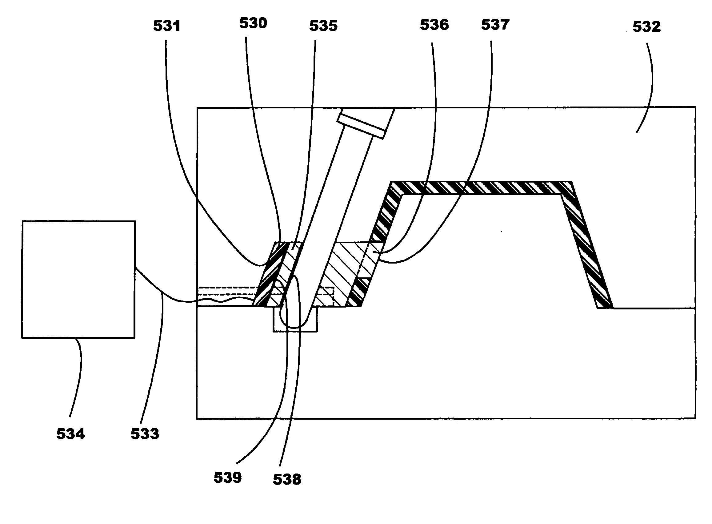
[0025]FIG. 6 illustrates a first preferred embodiment of the present invention as applied to the mold shown and described in FIGS. 1-5. A piezoceramic device 530 is attached to a wall of a recess 531 formed in cavity block 532. The piezoceramic device 530 is preferably aligned within the recess 531 so that it is adjacent to a surface of side acting insert 535 within the mold. The piezoceramic device 530 is connected to a controller 534 by a conduit 533, although wireless methods of control are also possible, thereby providing actuation signals to the device 530. The piezoceramic device 530 is oriented such that it expands against the surface of the side acting insert 535, thereby allowing the actuation of the device 530 to press the side acting insert protruding form 536 securely against the core side wall 537. It is also envisioned that the device 530 may be positioned in other locations within the mold assembly, so long as the location allow...

second embodiment

4. The Structure of the Second Embodiment

[0033]FIG. 7 illustrates a second preferred embodiment of the present invention. A preform mold stack 540 includes a core 541, cavity 542, gate insert 545 with hot runner nozzle 546, and two side core inserts 543a and 543b typically known as neck ring inserts. Each side core insert 543a and 543b is mounted on a movable slide rail 547a and 547b respectively that are retained by gibs (not shown) on a movable stripper plate 549. A wear plate 548 fastened to the stripper plate 549 provides a suitable surface on which the side core inserts slide. The slide rails 547a and 547b, and consequently the side core inserts 543a and 543b mounted thereon, are moved perpendicularly with respect to the center axis of the stack 550 by cams (not shown) in a conventional manner during the ejection portion of the molding cycle. The taper locking surfaces 551a, 552a and 551b, 552b, respectively, of the side core inserts 543a and 543b wear as previously described w...

third embodiment

6. The Structure of the Third Embodiment

[0038]FIG. 8 shows a third preferred embodiment of the present invention. The preform mold stack 560 is similar to that shown in FIG. 7, but differs in that the piezoceramic insert devices 561a and 561b are positioned to apply a force directly against each side core insert 562a and 562b, respectively, instead of against the slide rails 563a and 563b, as is the case in the embodiment shown in FIG. 7. This means that in this embodiment each pair of side core inserts 562a and 562b can be directly acted upon by its own pair of piezoceramic inserts 561a and 561b. When the present embodiment is implemented in a multi-cavity injection mold, the controller 564 may be programmed to provide individual signals to activate each pair of piezoceramic inserts, thereby allowing each molding stack to be “tuned”. Thus, if molded parts are found to contain parting line flash that varies between the molding stacks in the mold, each unique variation can be individ...


PUM

PropertyMeasurementUnit
dimensionaaaaaaaaaa
electricalaaaaaaaaaa
pressureaaaaaaaaaa

Abstract

Method and apparatus for applying a force to a portion of a surface of a mold component are provided. An injection mold has a core insert, a side acting core insert, and a piezoceramic actuator. The amount of force needed for sealing a surface of said side acting core insert to a portion of a surface of said core insert is determined, and a piezoceramic actuator is actuated so as to supply the force to seal the side acting core insert against the core insert during a molding operation. A piezo-ceramic sensor may be provided to sense a force between the side acting core insert and the core insert, and to generate corresponding sense signals. Wiring structure is coupled to the piezo-ceramic sensor and is configured to carry the sense signals.

Description

BACKGROUND OF THE INVENTION [0001] 1. Field of the Invention [0002] The present invention relates to a method and apparatus in which active material elements are used in injection molding machine equipment (e.g., insert stacks), in order to exert a force on one or more side core inserts, urging them against the core side wall of an injection mold, thereby improving the quality of the molded article, and the life of the mold components. “Active materials” are a family of shape altering materials such as piezoceramics, electrostrictors, magnetostrictors, shape memory alloys and the like. In the present invention, they are used to adjust the positions of and forces exerted by side core inserts, thereby improving the quality of the molded article, and improving resin sealing. The active material elements may also be used as sensors. [0003] 2. Related Art [0004] Active materials are characterized as transducers that can convert one form of energy to another. For example, a piezoactuator ...

Claims


Application Information

Patent Timeline
Patent Type & Authority Applications(United States)
IPC IPC(8): B29C45/00B29C45/03B29C45/26B29C45/33B29C45/76B29C45/77B29C45/80
CPCB29C45/2618B29C45/2628B29C45/332B29C45/36B29C45/80B29K2105/253B29C2945/76013B29C2945/76257B29C2945/76458B29C2945/76505B29C2945/76936B29C2945/76006B29C45/03B29C45/77B29C45/26
Inventor NIEWELS, JOACHIM JOHANNES
Owner HUSKY INJECTION MOLDING SYST LTD
Why Eureka
Try Eureka