

Ring type current sensor
- Summary
- Abstract
- Description
- Claims
- Application Information
AI Technical Summary
Benefits of technology
Problems solved by technology
Method used
Image

Examples
first embodiment
(First Embodiment)
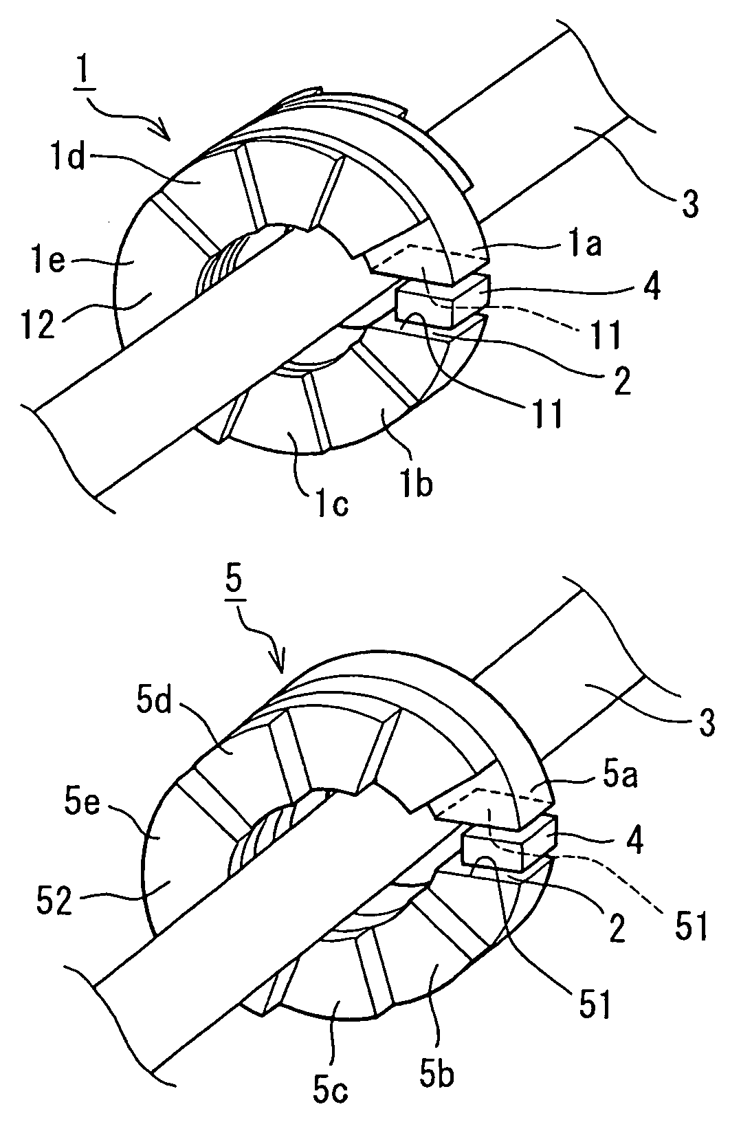
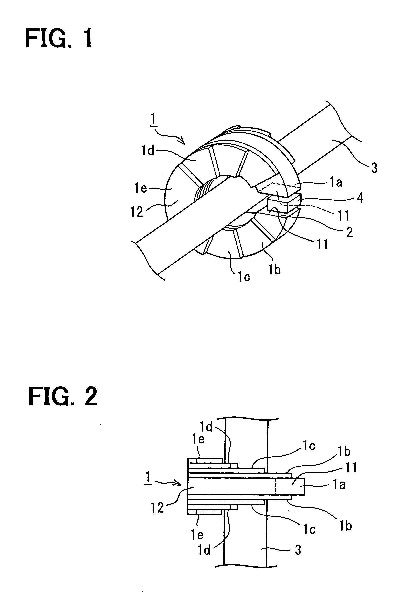
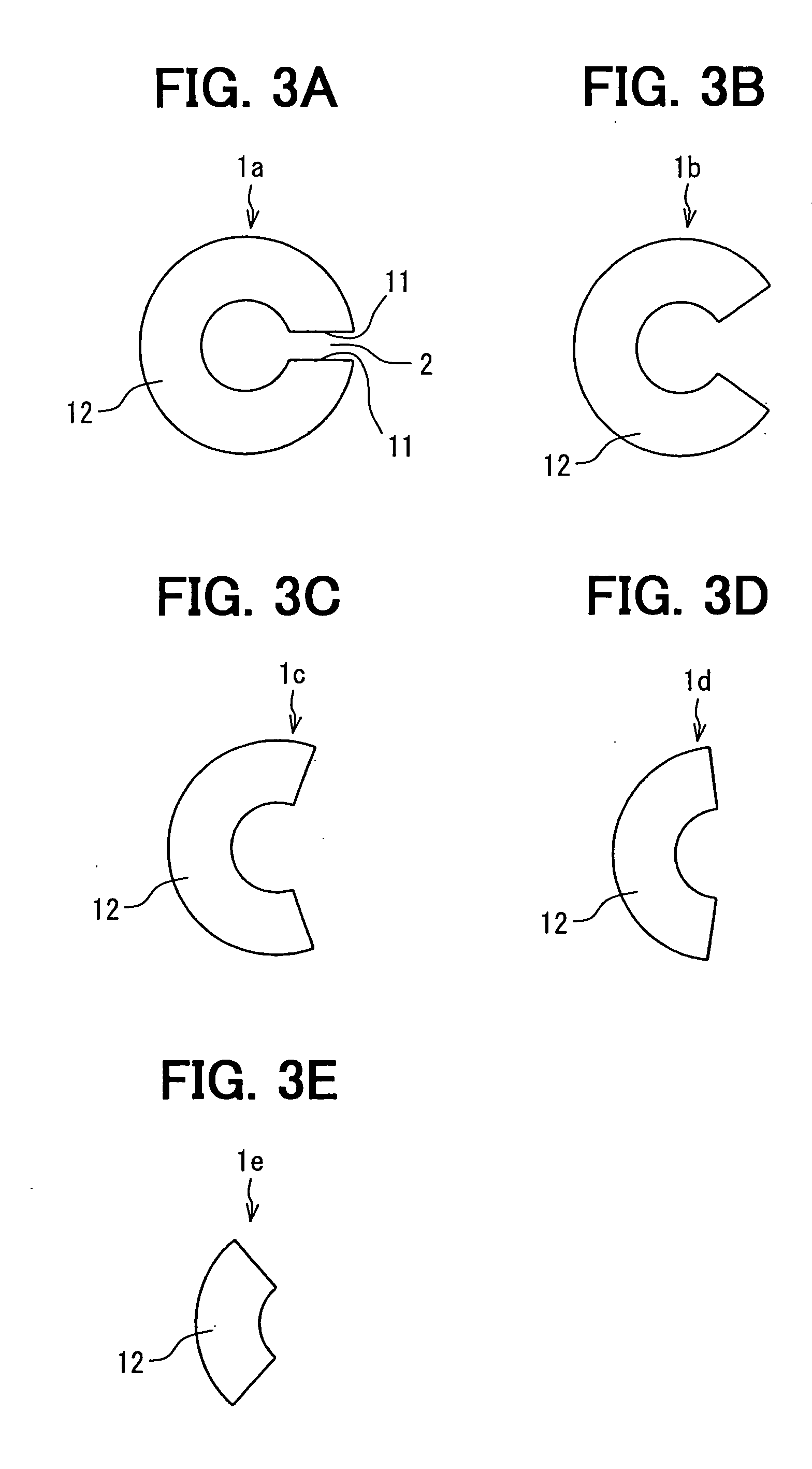
[0021] A ring type current sensor according to a first embodiment of the present invention, as shown in FIGS. 1, 2 and 3A to 3E, has a C-shaped core 1 provided with a gap 2 between both end faces 11 in a circumferential direction of the core 1. The core 1 and the gap 2 define a magnetic path therein. Both end faces 11 of the C-shaped core 1 are disposed in parallel with each other to uniform a clearance between both end faces 11 and a magneto-resistance distribution in the gap 2.
[0022] The core 1 encloses a bus bar 3 for flowing a current to be detected and disposes a magnetic sensor 4 such as a Hall effect sensing device in the gap 2. Specifically, the magnetic sensor 4 is disposed perpendicular to a magnetic flux flowing in the magnetic path to generate an output voltage proportional to a magnetic flux density in the magnetic path including the gap 2. FIG. 1 shows the core 1 and the magnetic sensor 4 to have clearances therebetween, however, a practical assembly...
second embodiment
(Second Embodiment)
[0028] A ring type current sensor according to a second embodiment, as shown in FIGS. 4 and 5, has a core 5 differently formed from the core 1 in the first embodiment. The ring type current sensor except the core 5 has the same assembly as that of the first embodiment.
[0029] An effective cross-sectional area of the core 5 perpendicular to a circumferential direction thereof gradually increases from a side of the gap 2 (from both end faces 51) to another side 52 in a diametrical direction of the core 5. Specifically, the core 5 is a stack including a plurality of core plates 5a to 5e. The core plate 5a has a larger thickness than those of the other core plates 5b to 5e. A set of the core plates 5b to 5e are stacked on a side face of the core plate 5a as shown in FIGS. 4 and 5. The gap 2 is defined between both end surfaces of the core plate 5a. The laminated stack of the core plates 5a to 5e are integrated by a fixing member etc. and / or glued with an adhesive made...
third embodiment
(Third Embodiment)
[0030] As shown in FIG. 6, a ring type current sensor according to a third embodiment has a core 6 having a shape relative to the cores 1 and 2 in the first and second embodiments. The core 6 is made of a highly permeable metallic material such as Fe—Ni alloy as the cores 1 and 5 are. An effective cross-sectional area of the core 6 perpendicular to a circumferential direction thereof gradually increases from a side of the gap 2 to another side 52 diametrically opposite to the gap 2. Specifically, the core 6 is made of a magnetically highly permeable metallic plate material by a winding formation.
(Other Embodiments)
[0031] The present invention described in the above embodiment can be modified as follows for example.
[0032] The core 1, 5 or 6 made of magnetically highly permeable metallic materials such as Fe—Ni alloy in the above embodiments may also be made of other magnetic material such as ferrite.
[0033] The magnetic sensor implemented by the Hall effect sens...
PUM
 Abstract
Description
Claims
Application Information