Apparatus and method for determining contact dynamics

a technology of apparatus and dynamics, applied in the field of apparatus and methods to determine contact dynamics, can solve problems such as false readings, other effects on the system, and limit the speed at which switches can be activated, and prolong the existence of arcs

Inactive Publication Date: 2005-10-27
IBM CORP
View PDF2 Cites 11 Cited by
  • Summary
  • Abstract
  • Description
  • Claims
  • Application Information

AI Technical Summary

Benefits of technology

[0019] In yet another embodiment of the invention a method is used to measure capacitance across at least two conductive surfaces. The method includes providing a movement between a first conductive surface and a second conductive surface. The method includes further, providing a high frequency signal across the first conductive surface and the second conductive surface and measuring the amplitude of the downstream signal at the second conductive surface. The measured frequency is converted to a voltage and translating the voltage into a waveform of capacitance versus time as the first conductive surface and the second conductive surface move with relation to one another to determine mechanical separation between the first conductive surface and the second conductive surface over a predetermined time period.

Problems solved by technology

Switch design is a well established discipline, however, two conductive contacts can collide and bounce back and forth until a steady-state occurs, that is, switch contact bounce, although recognized is not often characterized in detail due to lack of convenient low cost measurement methodology.
These digital signals created by the bounce may result in malfunctions, false readings, and other effects to the system.
These “debouncing” software routines set a limit on how fast the switches can be activated, since if they are activated during the debounce period, they are ignored.
In this type of system, the bounce of the contacts creates and / or prolongs the existence of an arc due to the high induced voltages that result when contact is broken.
This plasma arc tends to pit and wear away the contact surfaces over time which, in turn, affects the lifetime of the contacts.
However, each one of these techniques may be limited in its use to certain applications.
However, while high speed photography equipment may be reliable, it tends to be very specialized and costly for this application.
Moreover, the technique requires a high degree of setup.
However, this may modify the electrical insulation properties of the switch itself.
Also, this technique will not capture rapid mechanical movements, for example, on the microsecond time scale.
However, due to this relatively massive element, accelerometers are only able to sense the dynamics of larger (i.e., much more massive than the accelerometer) structures without corrupting the dynamics of the mechanical motion itself.
That is, the weight of the accelerometer may affect the dynamics of a smaller structure, like a switch, resulting in an inaccurate portrayal of the switch dynamics.

Method used


Image

  • Apparatus and method for determining contact dynamics
  • Apparatus and method for determining contact dynamics
  • Apparatus and method for determining contact dynamics

Examples


Embodiment Construction

[0029] The invention is directed to, for example, an apparatus and method of non-invasively monitoring dynamics of a switch and other structural elements. In one exemplary embodiment, the invention provides an apparatus and method for measuring and calculating distances and other dynamics of a structural or acoustic system over time. The invention provides a system which does not require line of sight access or significant modification to any system that it is monitoring, and may be used to measure in-situ dynamics of elements, for example, during operation without system performance degradation. The invention is applicable in a wide variety of applications to improve and / or monitor a system's performance over time. For example, the apparatus may be used in a wide range of switching applications, structural dynamic applications, refinement of acoustic transducers, or the like.

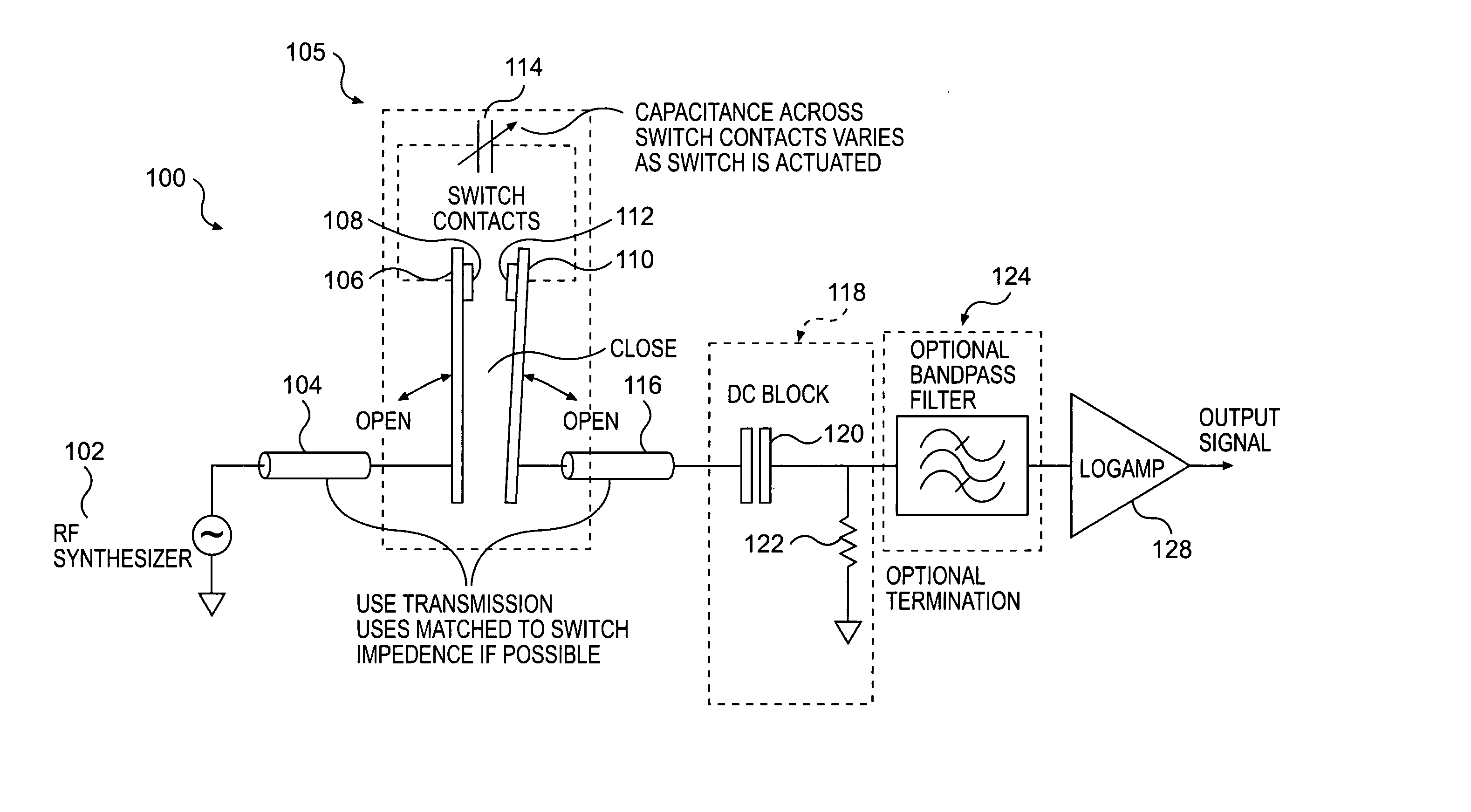
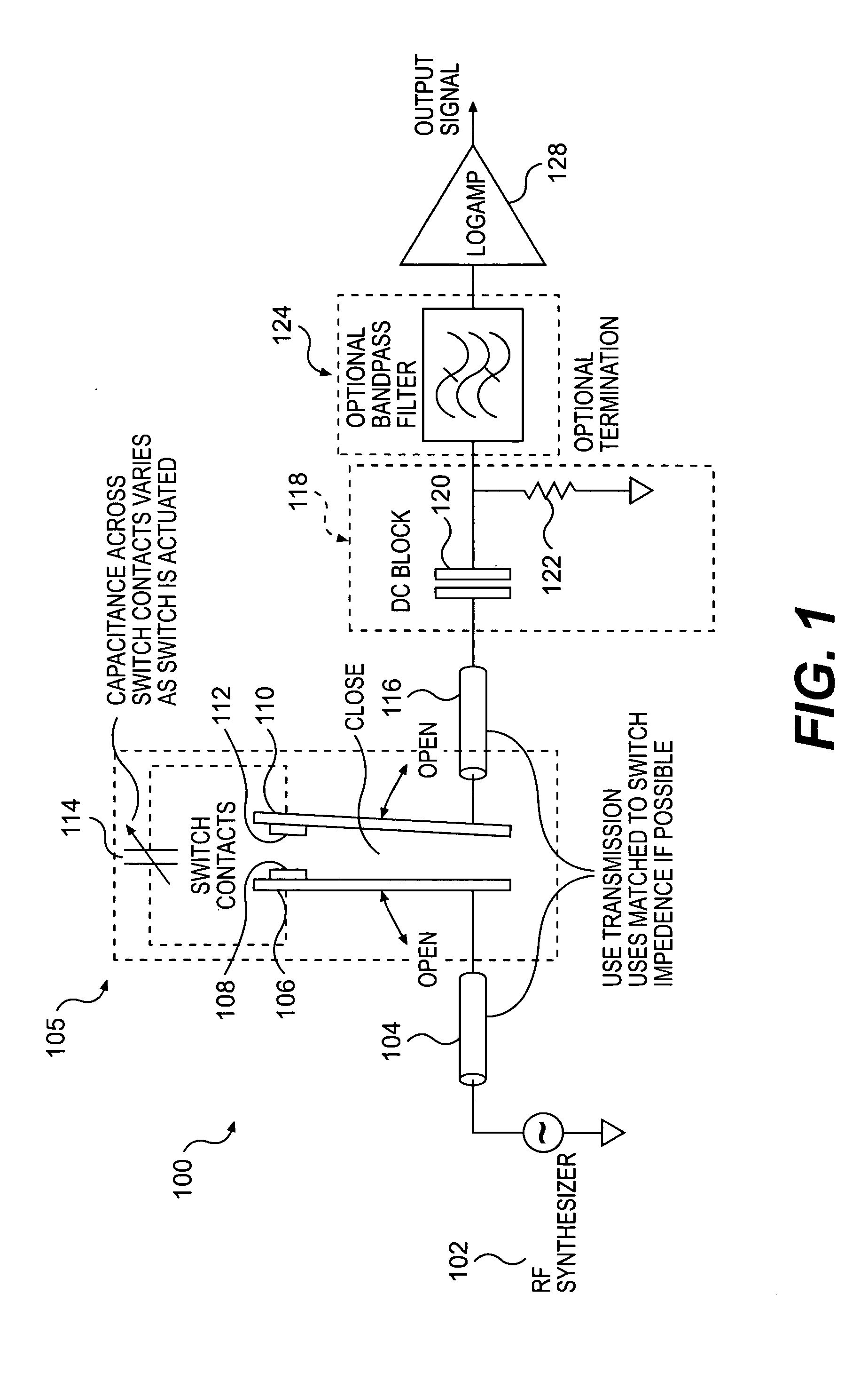
[0030]FIG. 1 shows an apparatus according to an embodiment of the invention. The overall apparatus is gener...


PUM


Abstract

The invention relates to an apparatus and method to determine contact dynamics between conductive surfaces, and more particularly to determine the dynamics of contact closure in mechanical switches and analysis of the dynamics of other mechanical systems, in general. A log amp is in electrical communication with the RF synthesizer via a transmission line. The log amp outputs a voltage converted from an envelope of an RF waveform to determine a capacitance between at least two conductive surfaces.

Description

BACKGROUND OF THE INVENTION [0001] 1. Field of the Invention [0002] The invention relates to an apparatus and method to determine contact dynamics between conductive surfaces, and more particularly to determine the dynamics of contact closure in mechanical switches and analysis of the dynamics of other mechanical systems, in general. [0003] 2. Background Description [0004] Switches are currently used in a wide variety of applications ranging from simple light switches to advanced microelectronic components such as RF switches using MEMs technologies. For example, mechanical switches such as toggle switches, rocker switches, and the like are used in a wide variety of digital, analog, and power systems. Switch design is a well established discipline, however, two conductive contacts can collide and bounce back and forth until a steady-state occurs, that is, switch contact bounce, although recognized is not often characterized in detail due to lack of convenient low cost measurement me...

Claims


Application Information

Patent Timeline
Patent Type & Authority Applications(United States)
IPC IPC(8): G01R31/02G01R31/327
CPCG01R31/327
Inventor KWARK, YOUNG HOON
Owner IBM CORP
Why Eureka
Try Eureka