Camera rotation support apparatus for video presenter and video presenter having the same

a technology of supporting apparatus and camera, which is applied in the field of video presenters, can solve the problems of reducing the size of the table for placing objects, difficult to locate the camera accurately on the center of the table, and known limitations of the camera support structure, so as to prevent free gravitational rotation and convenient adjustment and maintenance

Inactive Publication Date: 2005-10-27
HANWHA TECHWIN CO LTD
View PDF4 Cites 59 Cited by
  • Summary
  • Abstract
  • Description
  • Claims
  • Application Information

AI Technical Summary

Benefits of technology

[0018] The present invention provides a camera support structure for a video presenter, by which the orientation of the camera can be conveniently adjusted and maintained, and a video presenter having such a camera support structure. The camera support structure of the present invention can also prevent free gravitational rotation of a camera mounted to the support arm, even when the orientation of the camera is fixed in a horizontal position for long time and after extended use.

Problems solved by technology

However, in a conventional video presenter, such a camera support structure has known limitations as described herein below.
In this arrangement, the size of the table for placing an object can be reduced, but it is difficult to locate the camera accurately on the center of the table.
However, the elastic force of the springs 35a and 35b used for preventing the free rotation of the camera can be decreased from extended use if the camera is frequently moved, thereby incomplete fixing of the camera can occur.
In particular, due to the weight of the camera, when the camera is fixed in a horizontal orientation, the springs 35a and 35 may not prevent free rotation of the camera after extended use of the presenter.

Method used


Image

  • Camera rotation support apparatus for video presenter and video presenter having the same
  • Camera rotation support apparatus for video presenter and video presenter having the same
  • Camera rotation support apparatus for video presenter and video presenter having the same

Examples


Embodiment Construction

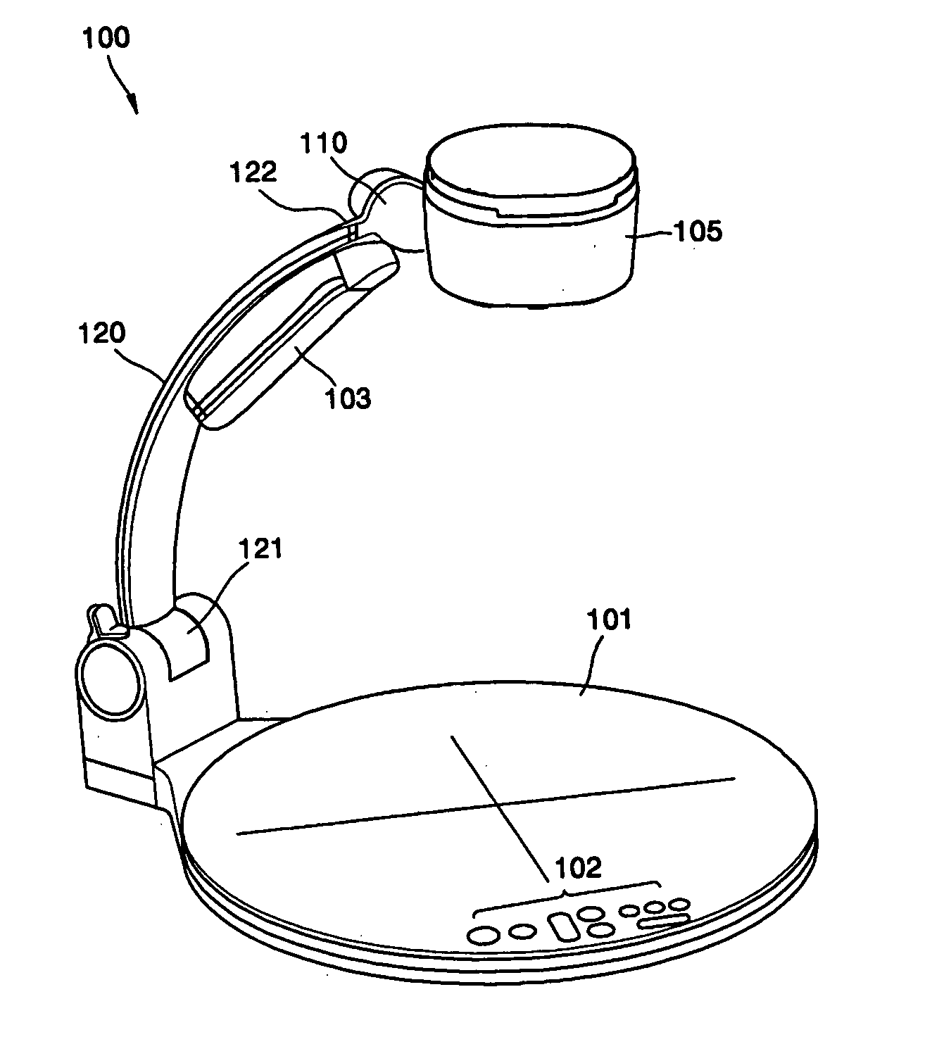
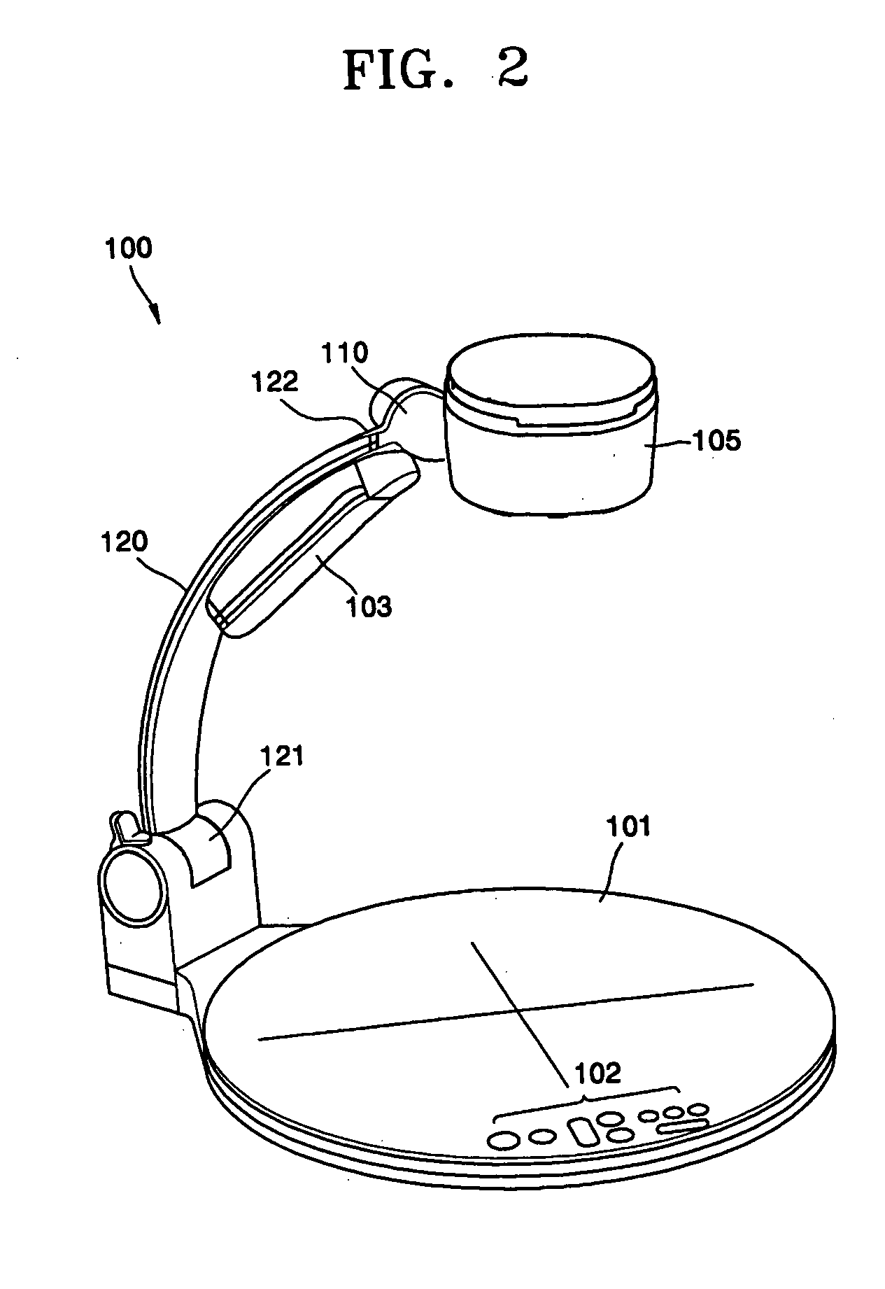
[0039] With reference to FIG. 2, an overall structure of video presenter 100 according to one embodiment of the present invention is illustrated and described herein. Video presenter 100 for inputting a video image of an object includes a table or base 101 for placing thereon an object to be photographed, a support arm 120 extending generally upwardly from the base 101, a camera housing 105 supported by the support arm 120, and a camera support assembly 110 that supports the camera head 105 in a manner rotatable with respect to the support arm 120.

[0040] An electric circuit that can control and process all operations of the video presenter 100 is placed in the base 101. Also, a control panel 102 is provided on an upper surface of the base 101. The operator can control the video presenter 100 by controlling switches in the control panel 102.

[0041] A lower end portion 121 of the support arm 120 is rotatably coupled with the base 101, and an upper end portion of the support arm 120 i...


PUM


Abstract

Provided is a camera support structure for a video presenter which allows rotation of a camera connected to a base of the video presenter and supports the camera in an accurate location. The camera support structure of a video presenter includes a support arm, one end of which is joined with the base, an rotation guide member that includes an annular member having a ring shape in which a plurality of ball receiving holes are formed on one end part of the support arm, biasing elements that includes a plurality of rotation-fixing balls which are inserted into the ball receiving holes from an inner side of the annular member and a portion of the balls are elastically protruded to an outer side of the annular member, a annular plate element, the rotation of which can be prevented by fixing by the rotation-fixing balls and disposed to be able to be rotated on an outer side of the annular member of the rotation guide member, and a camera head that rotates with the annular plate element by coupling with the annular plate element and fixes a camera head having a camera.

Description

[0001] This application claims priority of Korean Patent Application No. 2004-28729, filed on Apr. 26, 2004, in the Korean Intellectual Property Office, the disclosure of which is incorporated herein in its entirety by reference. BACKGROUND OF THE INVENTION [0002] 1. Field of the Invention [0003] The present invention relates to a video presenter for inputting a video image of an object, the presenter having a camera support structure allowing adjustment of camera orientation. [0004] 2. Description of the Related Art [0005] A video presenter is a device that typically uses a charge-coupled device (CCD) camera and a magnifying lens to display images of an object on a display device. [0006] The video presenter can be manufactured in a variety of configurations according to the supporting structure of the camera. The camera supporting structure has an adjustment function for allowing the CCD camera mounted on the support arm to access the object from various angles according to the des...

Claims


Application Information

Patent Timeline
Patent Type & Authority Applications(United States)
IPC IPC(8): G03B21/06G03B17/56H04N5/225
CPCH04N1/19594H04N2201/0446H04N2201/0436H04N5/2252H04N23/51A47K11/035
Inventor LEE, SEUNG-YEOBCHO, HYUN-WOO
Owner HANWHA TECHWIN CO LTD
Why Eureka
Try Eureka